I think that mapping areas - whether the whole dike or just the slope - is not a good solution. At least with regard to a possible rendering.
In our data model we only have closed polygons for areas.
such areas then compete in the rendering with other areas, e.g. landuse=*
skillion roofs are not huge areas, clearly delineated and in most cases they have a clear direction. Dykes and embankments are often not straight but have frequent changes of direction. Either the direction of such an area cannot be specified exactly or a dike has to be divided into many shorter sections. This is not KISS
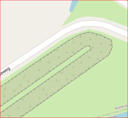
if you only want to render the edge again, you have this effect again:
With surfaces it is also difficult when a dike or dam merges into a natural elevation (e.g. dune).
Also other tagging aids like giving dike height and slope becomes difficult to determine on the ground. What is the basis for determining elevation? The sea level? The natural ground - to the right or left of the dike? The water surface? This is all nice to have, but not KISS.
I would prefer to leave the man_made=embankment for the embankment edge at the level of the top of the dike as it is.
I welcome a proposal to find a tagging for the toe line ( I think in Germany we say “dyke foot” for it) - e.g. man_made=toe_line. The toe of the dyke is, as @Peter_Elderson describes, usually easily recognisable, at least on land. If the toe line of the dyke is under water, then visually the riverbank is the relevant line (and toe line does not need to be mapped additionally).
The toe_line is easy to map and, depending on the quality, even recognisable on aerial photographs.
The only thing left to consider would be which rendering to propose for it.
The consideration of @SK53 goes in the right direction. It should just be a bit finer. I would just not render these differently sized depending on the slope.
For the toe_line, I can imagine small short fine strokes in the upward direction of the slope as a rendering.
If it should be technically possible - I have no idea, but I can imagine it - one can combine the (opposite) embankment and toe_line into a relation and a renderer can perhaps generate a hatching from it, as it is usually known from other map and CAD representations.
This is wrong in my eyes, it should always be the edge at the top.
Nederland has the term dyke foot, which includes part of the slope ending with the toe. I think the image is that the outer slope (water side) is steep like a heel, and the inner slope is like the front of the foot, ending with a slight elevation: the toe. Most of the time you will not see the toe elevation, because it is covered with soil, sand or grass. I am told that the expert eye can spot the toe easily on aerial photos and in the field. Since it is part of the construction that needs insoecting and maintaining, it cannot be fully covered without special constructions (concrete and steel, probably).
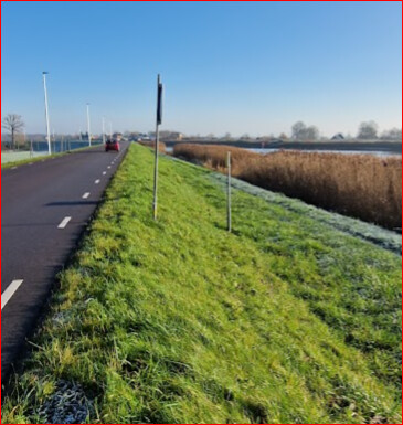
Btw, on our high dykes, the slope always has a flat section, often with a track on it, for dyke inspection and maintenance. Or not a track but a cycleway or minor (service or unclassified or even residential) road.
Example (my own photo, surveying a hiking route)
To the right of the track, the dyke has a reinforced_slope of about three meters, then a reed field sloping another 3 m down into the river water. The river level is tidal and also varies with rainfall upstream. The land-side of this dyke is much larger, because the land is yet several meters below the river level. This is one of the main dykes protecting my house, which is near the lowest point in Nederland, nearly 7 m below sea level. If this dyke breaks, only my solar panels and the chimney wil be visible above the water, and I’ll be sitting there with my wife and children!
The idea of representing the extent of an embankment (of a dyke or any other type) by two lines instead of an area would surely also be an acceptable solution but nevertheless the embankment IS an area and that’s why I believe it’s worth to think about tagging it as such. I am quite sure there will be ways to render the slope area, starting from the top line indicating the direction of the slope.
Anyhow I am aware that those extended dyke embankments being covered in parts with housing or commercial/industrial objects, roads, tracks etc. will not be easy to handle. From that point of view a solution ignoring the area and just indicating the toe line by an additional way with an appropriate tag has some charme for sure.
Maybe some misunderstanding? Peter wrote:
When looking at the embankment on each side of the dyke separately one can surely estimate the height of that very side from toeline to crestline. The same is done for other man_made objects which are difficult to measure as well and it is a valuable information imho.
I think this problem arises always when different landcovers merge. When the embankment of a dike is subject to a certain landuse like meadow no surface tag is needed. If it may be reinforced by rock for instance an additional tag surface=rock would not do any harm
Sure but even the wiki is not clear about this issue and the 200K embankment ways already mapped could well represent the toe line or even lie in the center of the slope. If a new tag for the toeline would be introduced now the documentation in the wiki should get some update with clear definitions where to place the ways.
I don’t think limitations of how we currently do things should affect what & how we map.
The precedent of mapping cliffs as areas is at least 12 years old, and I think things like defensive-work=glacis also come into this “mapping of slopes” issue, although most of the ones I could find a are also tagged man_made=embankment and are lines. Another example is a very wide set of steps (where area:highway=steps) can be used.
I think we DO miss the possibility of adding something like a width tag to a line (not width, because the convention is to map the top a sloped element) which denotes the distance from the top of the slope to the toe line. (Obviously this would work better with regular artificial constructions than cliffs).
For those interested this picture might be an illustration for what Peter accurately describes as the Dutch living on the bottom of a bath tub: here is the best example photo I could find from my surveys that might convey this (Mapillary):
Please keep in mind that the canal is not like an aqueduct that is constructed above normal ground level: the canal is below sea level and we dug out the bordering land even lower (fossil fuels were popular in previous centuries as well…)
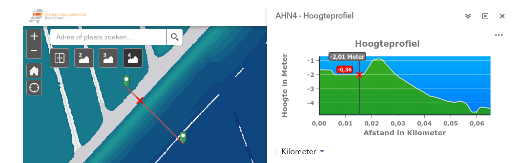
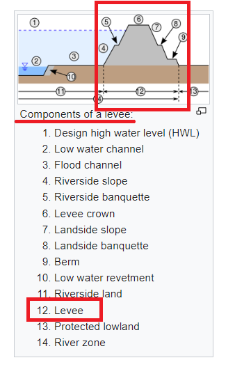
Cross section
Here you can see a lidar-cross section of such an embankment nearby (not this exact location since the buildings mess up the cross-section)
Source: AHN-viewer
On the left side:
Map with:
-grey: water
-blue: low-lying land
-green: high-lying land
-red line: the cross section (that you see in the image at the right)
-red cross: the border between the canal and the outside slope
On the right side:
Cross section:
-The flat section left of the red cross is the water level of the canal ( 2 meters below sea-level, the slope under water level and the bottom of the canal is not depicted)
-Directly at the right of the red cross is the outside slope of the embankment
-The crest is 1 meter below sea level and less then 5 meters wide
-The inside slope is about 25 meters wide (well defined and visible in the landscape) and goes down 3 meter
-Then there is a ditch and beyond that the flat inside the polder
This embankment is a circular feature with a circumference of some 30km
(and 25 m wide, so approximately an area of some 750 000 m2)
You need no knowledge to spot a crest; some awareness to spot a toe especially where it’s a bit hidden, and real expertise to see the complete dyke structure. I want to accommodate that in levels of mapping: all mappers can map the crest; more experienced mappers can map the dyke toe if they want; if the slope has special characteristics which we think should be mapped as a polygon, that’s an option; and it is also possible to combine an existing crest line and toe line to form an area.
About other uses e.g. the glacis, if a sloping feature can be called an embankment with a crest and a toe, you can apply the embankment mapping. The glacis, possibly, though I can’t be sure that experts in that field would be satisfied with that teminology. But they could use the same mapping model, with more appropriate terms.
Step areas, same thing: I see a toe, a crest and a slope. The slope has a step part, which is probably mapped as one or more ways. Combine that with a crest line and a toe line, and I think it can be rendered reasonably fine, showing on the map what is there. Other attributes of the step area would probably warrant mapping it as an area. Such as, surface, name of the complete area, exotic form of the sides of the area, separate steps combining into one, that sort of thing.
One thing: the glacis and the oversized steps have well defined sides, and occupy a limited area. The side lines probably have their own attributes, e.g. retaining wall, fence, kerb, hedge. So the last option I gave above will probably apply sooner than with dykes: “It is also possible to combine an existing crest line and toe line to form an area.”. This then evolves into: “It is also possible to combine an existing crest line, toe line and side lines to form an area.”.
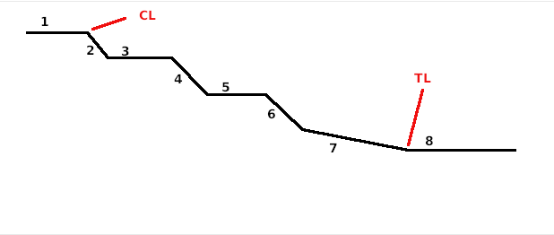
I think I understand what you are going for and I believe your dykes are well worth a better tagging than just man_made=dyke, but I still see a problem in the definition of the terms and tags used. Your topic titles “Mapping embankments” but the concern is “mapping dykes” which is something different to my understanding. Looking at a surface structure like this:
This could be a cross section of an agriculturally used hillside, lets say grape cultivation. In this case you would tag no. 2, 4 and 6 as embankment, whereas 1, 3 and 5 are the flat terraces where the grapes are grown and (therefore not part of the embankment). These embankments have a more or less linear appearance and would be sufficiently defined by a way with man_made=embankment (which is the standard at present). No.7 could be part of the embankment no.6 but could also be the remaining part of the natural slope.
If that profile would be of natural origin instead of man made the tagging would be very much the same by using natural=earth_bank instead of man_made=embankment for the sloping areas.
Again the same could also be a cross section of a dyke with some terraces carrying traffic ways or buildings etc. In this case (as far as I understand) you would like to mark the whole surface from 2 - 7 as “area/slope of the dyke”, with CL being the crest line und TL being the toe line. For a dyke this would definitely be correct imho as the dyke structure includes the flat areas as well as the steeper ones.
If that is your target, the use of man_made=embankment to mark the crest line only would not be correct, because this tag does not indicate a line but represents the entire area of the embankment (which in most cases has some linear appearance). Furthermore you would have to split the slope area into several sections representing the 3 embankments (in the above sample).
So instead of using the embankment tag for your dykes it would probably be better to find additional “dyke” tags? Starting for a normal small dyke with a single way tagged as man_made=dyke … going for more details by replacing this single way by 2 ways for the crest line and the toe line and probably using some tags like man_made=dyke + dyke=crest_line and man_made=dyke + dyke=toe_line …??.. or anything else going into this direction.
This would suit the special structure of your huge dykes much better than trying to map these structures by using the embankment-tags for it imho.
Embankments, such as dykes but also embankments carrying roads and railroads, and one-slope embankments. The fact is that OSM has defined the tag man_made=embankment as a line indicating one crest line for one slope down the right side of this line. Which is fine, because often only one side of a full embankment qualifies for useful mapping. If two sides qualify, just map both sides. Can’t get more flexible than that, and it preserves all existing data without any alteration. Yes there can be some confusion when talking about an embankment. I wasn’t sure when I started the topic, or I would have specified it in the subject line of this topic, that we will continue the one-sided approach, and where necessary just map two sides separately. Then it doesn’t really matter if a dyke is one or two embankments, and if our bosom canals have a full (two-sided) dyke at each side, so in fact two crestst, four crest kink lines, four slopes and four toes. You just map the slope or slopes that you feel need to be mapped. And you map them as simple or as rich as you want; keeping in mind that a renderer can only render the information you enter.
So far, I see no special case for Dutch dykes, except that they will often need the richer mapping (crest to toe) to provide the necessary information.
The thing we want to add is where the embankment slope stops, especially when the situation gets complicated, which often happens.
About the flat sections in a slope. Train and road embankment usually do not have these, large dykes usually have one flatter section in the slope. This may or may not be worth mapping separately. If there is a road or cycleway on it, one would assume that the slope stops at the road side, and if it resumes at the other side, you may want to map it as another man_made=embankment line. A toe line would only be necessary if the mapper thinks it is worth it.
If it’s not a dyke but a series of flat terraces with embankment slopes in between, you may want to map the slope toes to show how much flat terrace there is between the slopes. Fits perfectly in the embankment crest-embankment toe model, no matter if it is implemented as an area or as two separately rendered lines. Again, if the landuse of the terraces differs clearly from the slopes, you may not feel the need to map the toe lines.
( That is not-mapping for the renderer, I think? Which is fine with me, it happens all the time in OSM-wonderland.)
Maybe I misunderstood your intention. What I got is that you want to map the extent of your dykes by adding some kind of a toe line so that by appropriate rendering this can be displayed on maps. You also said that on the crest and the slopes of a dyke one can find lots of objects like houses, farms, traffic ways, agrigultural areas and the like. Many of these objects require some flat sections within the slope area. These flat areas in my opinion are not part of an embankment but still part of the dyke.
That is why I would see the most simple solution in not creating a new additional embankment tag but a new additonal dyke tag for the toe line. But that is just my personal opinion - other mappers will surely have other opinion about this issue.
Embankments including dykes. At this point, the thing that matters is adding a renderable element to mark the end of the slope. I think a new tag is needed, but which tag exactly s not really that important. For dykes the foot/toe metaphore is used, but other slopes could have a foot and toe just as well, dykies cannot exclusively claim a metaphore!
I think one new tag should suffice for a line solution. With an area solution the renderer would have to consider the crest line to determine the slope direction, but I think it’s complicated to make that work in rendering.
If the lower edge of the area or outline has to differ in apearance from the upper edge, a way (and new tag) for the lower edge is still needed, in addition to the area, I think. Maybe a renderer will correct me if I’m wrong!
The side edges do not need a separate tag other than the polygon itself.
If you think in slopes, a platform on the crest, buildings on the slope, splitting of the embankment, interruptions of the slope, widening of crest and/or slope, are not a problem. It doesn’t matter if you call it part of the dyke or not. You just map the embankment slopes, and slopes can have varying forms. For complicated configurations I think there is always a way to split them into separate, much more simple, slopes.
think simple, stupid! it should be a tag not only for dikes but for all types of embankments / man maked slopes. @Peter_Elderson wrote in his first post:
Of course, dikes are most important for Dutch people. More important than road embankments in mountainous terrain.
I fully support Peter! Let’s map a line where the embankment meets the ground level. Let’s find a term as simple as possible that describes this line as universally as possible, whether it is a dyke, embankment or road embankment and in the same way the lower line of a cutting.
And let’s convince the renderers in the next step to render this line in a suitable way.
Ich gehe jetzt einfach mal davon aus, dass diese Aussage eine Verballhornung von Keep it simple and stupid sein soll und keine persönlichen Beleidigung, auch wenn sich das sehr leicht missverstehen lässt.
Ich habe kein Problem mit einer embankment-Lösung, bleibe aber dabei, dass für mich eine Böschung und ein Deich unterschiedliche Objekte sind für die es ganz zu Recht auch unterschiedliche Tags gibt, was nicht heißt, dass ich nicht jeden sinnvollen Vorschlag dazu unterstützen würde.
Discussing complicated questions with people in the same language is already challenging enough, I think but this example below shows that even (or especially?) with help from translators an extra dimension appears:
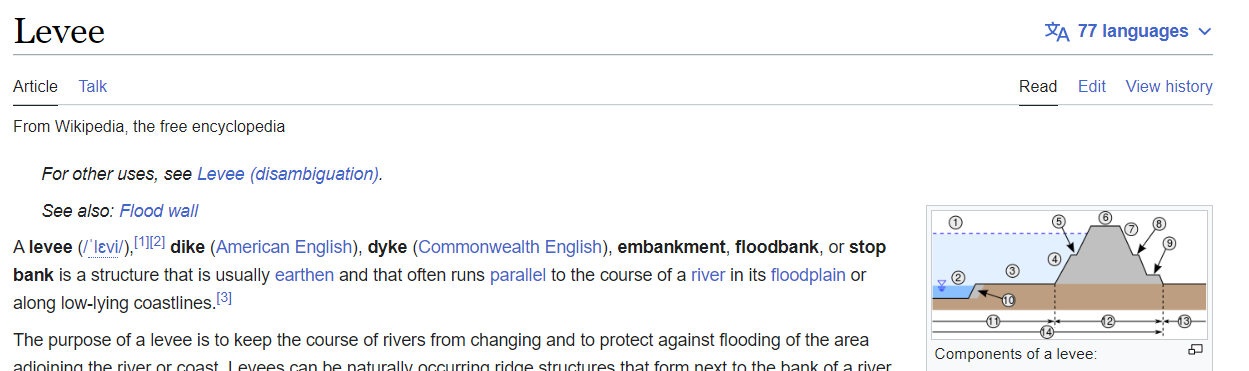
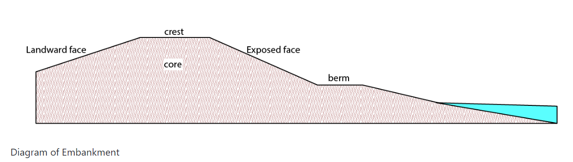
An embankment is an earthen structure used in the fluvial, tidal and costal environments for flood defence and/or erosion protection. Also covers embankments used in dam structures.
Just to be clear - the terms that they use appear to be terms with a specific meaning within the processes that the EA uses when building flood defences. At best, some of them are adaptions of general English Language terms. For example “berm” normally means “long linear pile of something”. Here is an example within OSM that follows that general usage. A different specialist usage is here, where it’s been used for a specific constructed feature. Corporate language evolves like that and sometimes is no longer intelligible to someone not familiar with an organisation’s “dialect” (as an example, think about the “TPS Reports” in the movie Office Space).
I wouldn’t use words that the EA has used that also mean something else in more general language, I’d pick something else.
Underscoring the tone of what I believe is clearly everybody’s best intentions: it is terrific when people discussing something relatively complex (dykes, embankments, berms and how they might be improved with OSM tagging and eventually rendering…) do so knowing that there are cultural and language challenges AND that all here go out of our way to both recognize that and respect that.
It does appear that there is “a great deal of light and almost no heat” in this discussion, and I write these words to simply congratulate everybody on excellent communication in our endeavors to achieve consensus: “nice job so far, everybody.” I can see the dedication and deeper levels of understanding and “transmission of thoughts” between ourselves, and it is good. Words in cyberspace in multiple languages can be fraught with difficulty, yet we overcome these difficulties quite well right here and now. That only happens with good intentions, which it’s clear we are extending.

