Mapping embankments

The Dutch community is discussing better/additional mapping for embankments. Since Nederland has over 17K kilometers of dykes to hold the water out and in place, plus a lot of embankments to carry railways and roads, embankments really define the landscape in large parts of the country.

Currently embankments are mapped as a crest line only, tagged man_made=embankment. Some mappers also map the toe line as man_made=embankment.

I am thinking of proposing a tag for a way representing the toe line of the embankment. That is, the line where the embankment slope meets the ground level, to allow better representation of the embankment. The main goal would be to enable better rendering including the extent of the slopes, which is now impossible because the information simply isn’t there.

Any thoughts on the subject are welcome!

2 Likes

I’m just wondering how exactly this will be rendered if it’s two separate lines parallel to each other. (If I understood you correctly?)

Wouldn’t it then be better to draw one area surrounding the entire dam?

2 Likes

That would be a toe line surrounding the dam, I think? Are you thinking of an existing tag for this area? And how would that help the rendering?
Keep in mind that these embankments are very elongated and often asymmetric features, not like a dam across a river, but like an embankment along the full length of the river.

It seems like you want / need to invent a new tag, perhaps embankment_toe_line or embankment:toe_line, consider implications for each. As you do, you’ll want to think about how the embankment key will both stay the same and might change, AND (it is entirely a separate issue) how the embankment key might need to change in renderers, along with your new key. It’s a whole package of considerations: the new semantic, the relation to an existing semantic (you don’t want to break “plain old” embankments as they exist today, but you would want them to take advantage of your new key) AND you’d likely need to be able to make smart suggestions to any renderer that wants to support both keys.

After thinking about all that, you might begin a new Proposal for a new key. I don’t read Dutch, so I haven’t read the linked thread; it may be that similar strategies ahead are already there (in Dutch).

1 Like

I think I’m mistranslating “toe line” in this context. Here is a random example in North Germany.
The crest (the highest point, like a ridge) of the dam was tagged here with man_made=dyke. The grass area with landuse=grass and on both sides of the dam runs a highway=track.
What is probably missing here is an embankment=yes.

Area in Bing (with OSM data overlay):

Area in Carto:

“Toe” in my case is a component of the foot, that is, at the bottom of the dam. So you would like to draw two more lines at the level of the two highway=track and mark the lower ends of the dam, do I understand that correctly?

That is a yes, but.
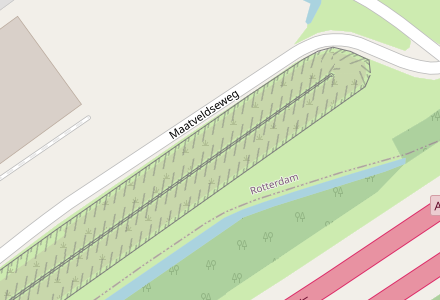
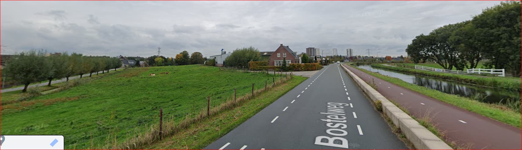
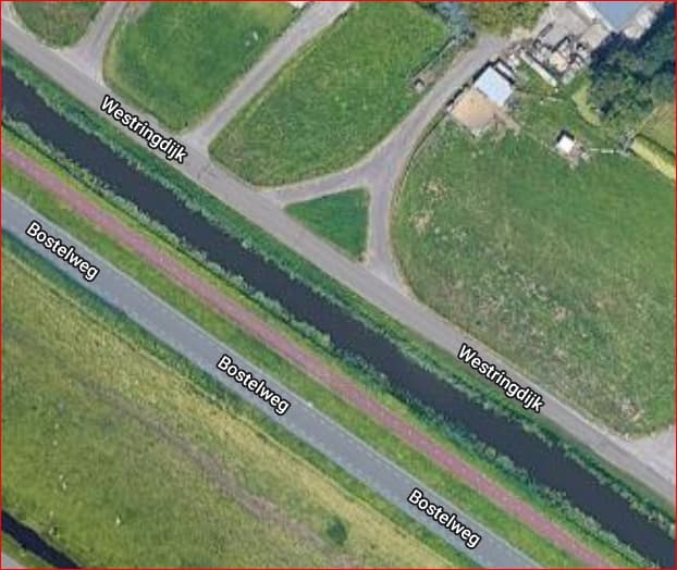
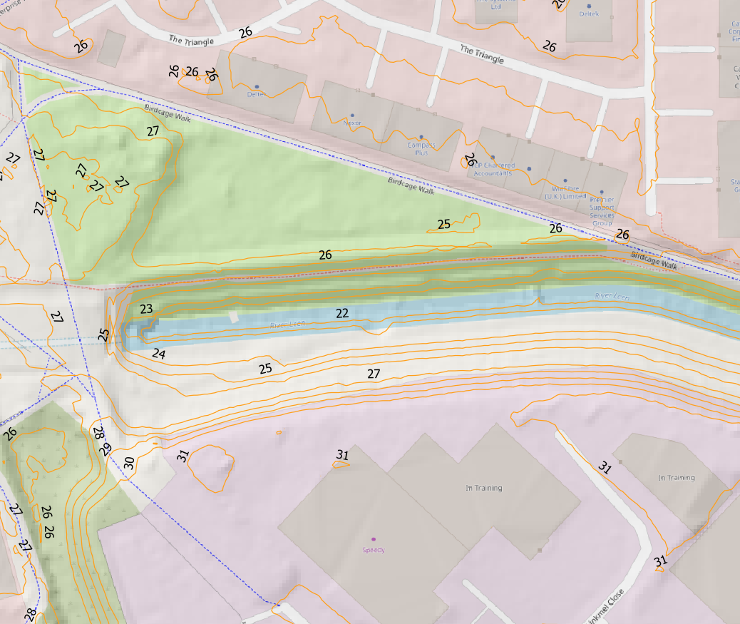
The toe line is where the dam meets the ground level. The Dutch discussion has some nice pictures (and there is the wonderful Discourse translate button!). E.g.
image
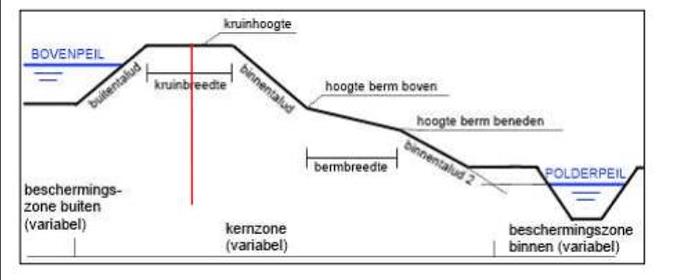
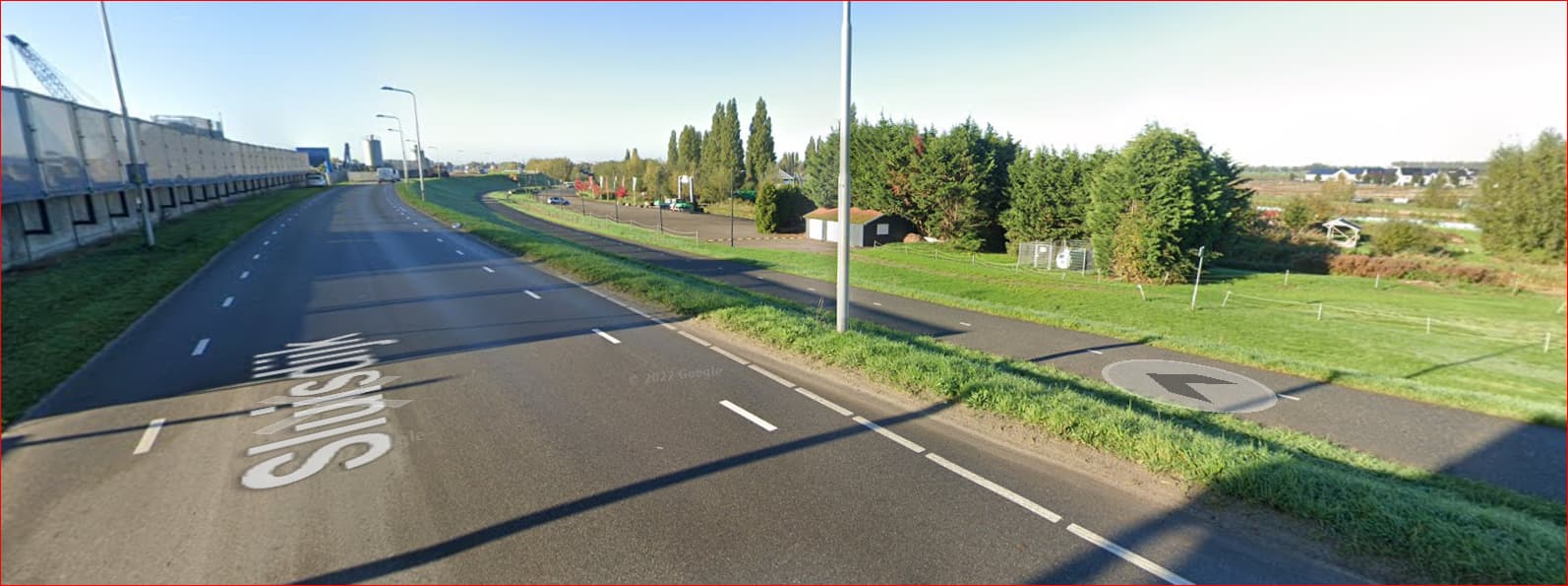
The right side slope has an upper slope and a lower slope. The lower slope ends on ground level, and it’s often is visible line in the landscape.

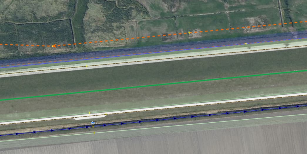
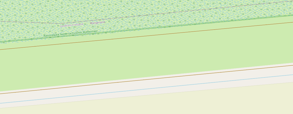
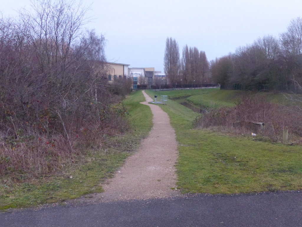
If there is a long way or waterway feature alongside, the toe line will be not too far from the edge the feature, and most mappers would feel that an extra line would be overkill. But most of the time, it’s not that simple! There may be water which may or may not rise with tide or rainfall. The toe line is often interrupted or covered by meadows, water, wood, houses, crossing infrastructure. The top op the dyke may carry a path, a road, a railway or have a canal embedded. The slope may be flattened to serve as a meadow. There may be a path or a road half way the slope.
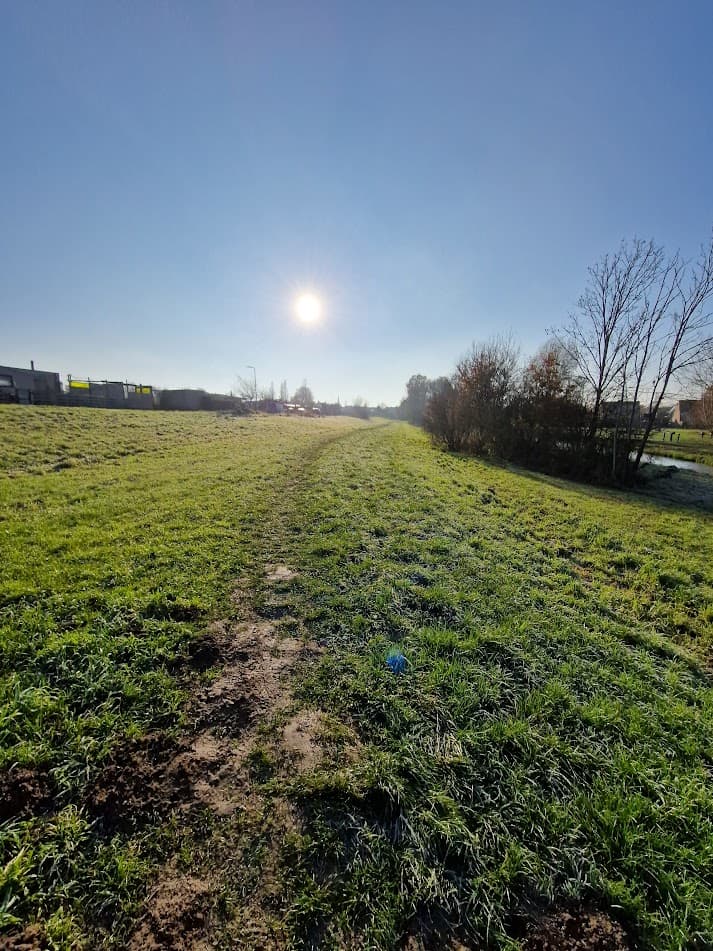
Or the dyke may have only grass on top, on the slopes and at both sides, so you can not tell by the rendering what the extent is.

The crest is usually flattened, so in fact you have two kink lines. In between may be just grass or bushes, or a path, track, or road. It may widen and contain landuse or buildings. If it carries a railway or a motorway, things may get very complicated…

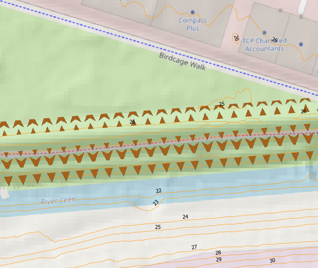
man_made=embankment seems to be defined for a one-sided crest line where the right side slopes downward. Renderers usually render it that way, and there’s a zillion uses. I see no need to alter that.

The idea is to look at one slope from a crest kink to the toe kink and indicate the extent. At the top with a way tagged man_made=embankment (existing) and at the toe with a way tagged …?
No obligation, but when the mapper feels it’s helpful, there should be a way to do it.
If it’s useful at one side of a dam, but not at the other side, which I think often will be the case with river embankments, lake embankments and sea dykes, fine.

There is also a mapper’s level / expertise consideration. Anyone can spot a crest, but spotting slopes/halfway levels/toes etc. is not that easy. It’s nice to have a build-up from just a crest line in the middle (man_made=dyke or embankment=yes, in use) to man_made=embankment (in use) to adding ??man_made=embankment_toe?? (to be proposed) to maybe further details visible to embankment experts.

1 Like

An annotated picture** of the sort of thing that you’re talking about here would really help here.

** Edit: Just to make it clear, I mean an actual photograph here (and not just overhead aerial imagery - something from a survey).

Of course it’s up to the renderer to come up with a rendering. It’s up to the mapper to make sure the information is there, and to document what it means, so that the renderer can express that in rendering.

In this case, as I see it, the toe line indicates where the slope stops, at the down side.
The simplest rendering would be just a thin line. Together with the crest line that will be clear to the map user in many cases, but not where it counts most: where it gets harder to imagine.
In those cases, there should be an indication of where the slope side is and where the ground level side is, similar to how the crest line indicates on which side the slope is and where the crest level is.

We have tried a few things, rather clumsily I’m afraid. E.g. simply reverse the crest line: the shark’s teeth or small side lines pointing upward. The result was that e complete dam, that is two slopes so two crest kink lines and two toe kink lines, looks like an elongated pit with a centre ridge!
image

We tried to alter that a little, still using the man_made=embankment all around a slope area.
Scheef talud 01
Slightly better impression, I think, but still only clear when you already know the situation.

Also, the situation that an area surrounded by a man_made=embankment really reflects a pit area is not uncommon:
image

To handle all situations, you really need the toe line to differ from the crest line.
Maybe a toe line with a bit of shadow at the high side would do the trick. I lack the skills to try these things.

I think I’m mistranslating “toe line” in this context. Here is a random example in North Germany.
The crest (the highest point, like a ridge) of the dam was tagged here with man_made=dyke. The grass area with landuse=grass and on both sides of the dam runs a highway=track.
What is probably missing here is an embankment=yes.

this is a rough representation but the dyke is mostly implicit, you cannot tell from the data where it ends (at the lower ends) or how wide it is, or how high.

| SomeoneElse Andy Townsend Support moderator
January 24 |

  • | - |

An annotated picture of the sort of thing that you’re talking about here would really help here.

here is an example from the web which illustrates why representing a dyke with a single line cannot convey the details, green area is the dyke:

https://www.ovb-online.de/bilder/2017/11/10/9278383/868929721-990_0008_164429_wald_deich_niederndorf_wasserwirtschafts-21a7.jpg

1 Like

I will see in my own pictures what I can find. Until now I didn’t explicitly survey this kind of thing, so a GS picture:


We are on a road on a river embankment crest. To the left there is industry on the embankment. The right edge of the road is the right crest line. A bit further down the slope there is a cycleway, then the slope continues down to a toe line. Then further to the right the meadows slightly slope down, and to the right, just in front of the residential area, you can see a bosom canal, which (I know) has embankment slopes on both sides.
If you look along the right hand slope of the dyke, you can see a relatively simple section showing the dyke structure. Whereas with the meadows, it’s much harder hard to tell where the dyke actually stops and the meadows begin. I know from my walks in this area that the extent of the bosom canal embankments is much less clear.


This is an embankment of the bosom canal (my own photo). To the left there is a slope, we are on a platform, and to the right there is a furher slope down to the ditch. It’s all grassland. Without a mapped embankment_toe line you cannot visualize the extent of the embankment. The houses you can see to the left are actually on and in the embankment, along a road on the crest of this dyke.

2 Likes

This shows a culverted river local to me, which I think shows the features wanted. The path in the foreground is here. These are flood defence features so slightly different.

To the left of the path there is an slope down to an area of grass and scrub. This area is broadly at the same level as the commercial buildings in the background. The path is an informal path (although recently re-engineered which is why I took the photo) along the top of the flood embankment (dyke). On the right the bank drops to a level which I think is somewhat lower than the ground level on the left, levels out and then drops again into the river channel proper. The profile is more obvious on the right bank. In normal flows the river will stay entirely within the channel, although the channel is graded to provide a broader cross-section in flood. In heavy flooding the extra space provided between the two embankments allows for much more water to be retained.

At the end of the informal path, the flood channel is narrower and the defences change slightly, with the left-hand embankment being replaced by a flood wall.

Most of these features are mapped, but not rendered, because embankment=yes is used on the path/dyke.

Having just tried to improve the accuracy of the path and other features, I’m not convinced that adding even more will make maintenance very easy. All of the embankment type features could be mapped as areas with use of the kind of notation used for skillion roofs (i.e., a direction indicating the downward slope), whilst retaining the grass tags already in place. I also note that exactly the same issue arises for cliffs, where a single way may be a very crude indication. I would suggest it might be more productive to discuss the more general case.

Thanks, nice picture! I’ll have to say, I would probably not map these banks at all. In my mind, I will scale it up say 5 times… I am living at nearly 7 m below sea level, and for flood protection the important dyke rings around our “polders” have to be up to 15m high. Since the sea is rising, flood storms will increase and the rivers tend to have highers high’s, plans are now being made to increase the dyke height even further, which also means they will widen further.

Now, on your picture, the river side is simple, I would just ignore the slope, considering it part of the waterway.
To the left of the path is a crest kink line. You could map that as a man_made=embankment, instead of the embankment=yes on the path. That would not increase maintenance, it’s just a different line.

So, the slope keft of the path. How exactly would you map that as an area? Which feature will carry the directional notation? I know the downward slope is to the right of the man_made=embankment, so you draw the embankment line toward the photographer, but how would you indicate where the slope stops and the level ground begins? I do not see this line in your picture, but I suspect the bushes in the front left cover the toe line.

Here is another example using GSV:

It’s hard to see elevation here, but the tree line at the left and the houses behind it are completely below the water level in the bosom canal. The slope to the left of the embankment is used as meadow, but further on there is housing and industry on the embankment. The crest is in fact the cycleway, the road is on the slope (the place of the road on the slope varies).

For OSM, I would place the man_made=embankment on the low retaining wall of the cycleway. BUt when I come to the housing the crest widens in fact widens or splits and the embankment slope goes all around it. How can you indicate with an area what the extent of the embankment is?

From the air you can see it running throug the meadow, and when you are ther and you have an eye for it, you can tell.


The other side of the canal is more or less the same story, only much more farms and steep driveways there.

My 2 cents: Why not keep the man_made:embankment tag as is and just add an area:embankment to it if required or wanted (similarly to the use of area:highway). You would not need to touch any existing tagging and also would not need to worry about how to indicate the direction of the slope.

Yes, this is in the spirit of my “subtag” comment above.

This is a great discussion with great pictures!

1 Like

Yes, but I posted the picture to illustrate the forms as requested, not to ask whether I should map it! It was mapped over 9 years ago, but these days we can align imagery better.

I suspect from water level to top of the embankment is about 5 metres (at least 4 from Lidar). The Lidar and derived contours help to show the form here quite well (which is the purpose of using this example)

The marked channel of the river is pretty much where the river flows. The grassy banks, on the other hand, are places I visit to find wildflowers and insects. The downside is that they are often mown by the Environment Agency at, for me, inappropriate times of year. the mowing is to prevent trees and shrubs growing as these may penetrate a geo-membrane under the slope. So there are good reasons to map these in this area. Looking at it more closely I was wondering why there was an embankment here, and realised when the culverted channel was built there was a large gun factory N of Birdcage Walk, and a railway serving the power station crossing the channel too.

But that increases the lines from 1 to 3. There’s nothing to stop a rendering engine using embankment=yes as a directive.

If I did want to map the extent of the embankments, I could map them as areas. I’ve done this for demo purposes in QGIS, and used a direction value to determine the orientation of the arrows on the embankment polygons (in principle these should be something like hachures, but I just wanted to show how a direction tag might work).

I remember discussion a “few” years ago about mapping slopes for hills & so on, which may have even gone to a (rejected) proposal?, but can’t find anything for it now.

Just “slope” is used, but not a lot: slope | Keys | OpenStreetMap Taginfo

Mapping embankment=yes on a way feature on the crest remains my starter’s option for simple cases. If there is no way feature on the crest, it doesn’t work. That’s where man_made=embankment comes in, which comes with directionality, so the crest becomes two lines. That comes in handy for the cases where the crest widens, curves, has buildings and landuses, is asymmetric, becomes a retaining wall at one side, etcetera. I have shown a few examples.
This increases the line count from one to two, I think. In your example, it would probaby be overkill, in many cases it is necessary to map ground truth.

Now looking at the slopes, you suggest using an area for each slope (or one area for the whole dyke?) What exactly would this area be? At the top I think the crest line (in your case the way of the path), and at the bottom the toe line, correct? Then, if you map one slope, somewhere there is an ascending part and somewhere a descending part. Of you map the whole dyke in one area you will in fact have to map sections, and you will have section lines with an ascending part and a descending part.

The direction values, I don’t understand. I probably lack some knowledge here. A polygon in OSM has one direction for the whole polygon, and you can’t assign different tags to sections of the polygon, I thought? If that is the case, the whole polygon will have one rendering, e.g. arrows pointing to the right side of the way. To my knowledge, you can’t have one part of a polygon showing arrows and another part hachures (and other parts showing nothing). In other words, for different rendering you need a different OSM object.

I very much intend to keep the man_made=embankment tag as it is.
I have a few questions about this suggestion:

  1. Is your suggestion to map the whole dyke (two slopes and a crest) as one area, with the man_made=embankment line in the middle? Or an area for one side of the embankment?
  2. Where exactly would I place the outline of this area?
  3. How would the area be rendered?