Mapping embankments

Mapping the upper and lower slope edges can’t be that difficult, various CAD software can do that too.

Examples

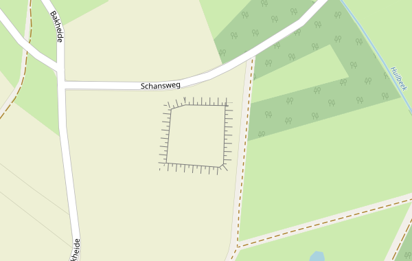
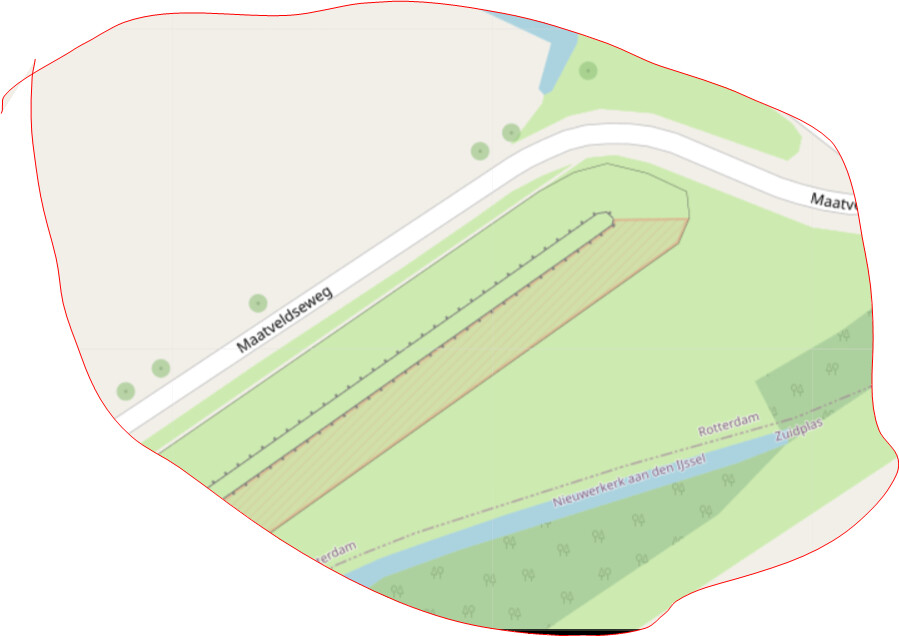
@Kogacarlo have already shown it here

Connecting the upper and lower line with fine strokes may not be trivial for renderers with the possibilities of OSM.

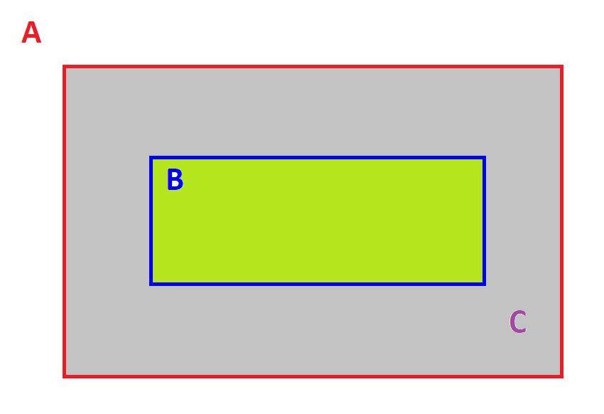
That is why I am thinking of rendering the two lines separately as a first step:
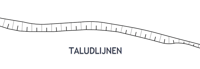
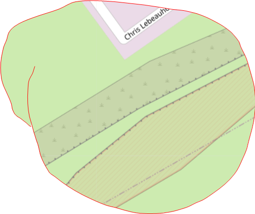
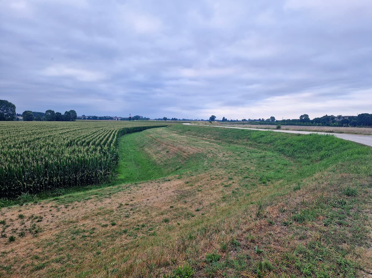
The upper edge (crest_line) of the slope (in the image this is the lower line!) has alternating shorter, thicker strokes and longer thinner strokes at somewhat closer intervals. This is - at least as far as I know - a widespread form of representation of the upper edge of a slope.
That this can be done easily has @Kogacarlo already been shown:

The lower edge (toe_line) of the slope (in the first image this is the upper line!) is to be mapped and rendered separately. This way has only thinner strokes at somewhat larger distances.

The length of these small strokes is to be chosen in such a way that in most cases they are opposite each other in the different zoom levels and at most touch each other. If they form a gap at larger distances, this is probably not a problem; a sighted person then unconsciously completes this in his or her brain when looking at a map.

In a second step, we can consider whether we can connect crest_line and toe_line with a relation and this enables a renderer to connect both ways with fine lines.

OSM Carto has a different rendering of man_made=embankment, just a line with some dots (giving the impression of shark’s teeth) at the lower side. Very suitable for a general purpose map. I see no reason to ask for a change there. I think the lower edge could be rendered even more subtle, to prevent railway-like appearance when top edge and bottom edge are very close (steep slope). A simple line (lighter than the top edge line, maybe a bit less sharp) would already show the extent and shape of the slope, and if there is a way to hint at the slope side very subtly, that would be a bonus. Actual non-scaling side lines - I think it’s too much.

I think connecting/separating side lines of lower and upper edge is not an issue.

To (maybe later) show the entirel slope as shaded or line shaded (Dutch: gearceerd, from the verb arceren) a relation with the top edge line and the bottom edge line woud be needed. Side lines can vary too, in complicated cases like the railway-crossing-canal example I gave. So we are talking about shading an area. As it happens, OSM already supports relations representing an area, and rendering such areas is pretty much standard.

Of course, I know.

My idea was to create a visual relationship between the two lines at the same time. That’s why I think the bottom line can look similar but still distinguishable and should have an additional mark that points upwards (like the teeth of man_made=embankment point downwards).

Further suggestions are welcome

I cannot render, but I can cheat to make it look like what I want to see! (aka mapping for the renderer.) Here I have an impression of an embankment with two different renderings.
The crest is delimited by the two crest lines, with just landcover between them. The north slope, I mimicked a double-line (white-gray) using a break in the grass cover and a feature that produces a gray line. (Note: because the white break scales when zooming, and the line does not, I had to choose one zoom level for the picture.)

The south slope, I used the line feature again, and this time I combined them in an area that has a rendering over the existing landcover.

I think the north slope subtly produces the right effect by just indicating where the slope stops. The south slope is not bad either if you ignore the colour, and it emphasizes the slope itself. It is a little too emphasized for my taste, on a general purpose map. I am mainly interested in the edges; the slopes themselves are just landcover.

Thanks for suggesting a couple of routes.
My preference would be a variant of option 2:

To take the simple example of a “free standing” embankment as a starting point:

In a schematic form this can be described as:

With the following features in the real world:
A : the embankment (the total of slopes + crest)
which consists of the following parts:
-B : the crown
-C : the slope(s)

To have a geospatial representation with the level of detail we all seem to aspire need two geometries:

  • the blue line (that traces the crown-line)
  • the red line (that traces the outside of the embankment ; in this case: the toe-line)

My preference would be to tag it something like

  • blue line (crown) : man_made=embankment ; embankment:part=crown_line
  • red line (outside of embankment) : man_made=embankment ; embankment:part=toe_line

Accompanied with an advice to renderers:

"most man_made=embankment without embankment:part=* are assumed to follow crown_lines; therefore it is suggested to render those as you do with crown lines

And in addition - to make the relations between the tagged lines explicit and allow for both better rendering and data-analysis (what is the area of slopes / crowns etc.) as an option :

- A multipolygon relation
with a new tag like area:embankment ?? (like area:highway)
Red line: role =slope
Blue line: role=crest

If it is already obvious enough from the main tag that the slope rises from from the outside to the inside, then these roles will suffice. If not the role for the red line could be slope:up or slope:down (seen from outside to inside) and for the blue line: crest or bottom
That depends on whether the main tag would include sloping pits (as opposed to elevations) as well, such as this example mentioned in wiki-Talk :

Disadvantages:

  • Not all mappers like to use man_made=embankment for the outline of the embankment

  • The optional multipolygon relations can be seen as complex by some

  • We have to figure out how well this model works for other cases (such as berms) and one-sided slopes (yet I think it is good to first find common ground for handling a simple case and after that take on more complex cases)

Advantages:

  • Avoids awkward tagging scheme / instruction in which the general term man_made=embankment is only used to trace the outline of the crown and not for the embankment as a whole (“trace the outside of the embankment and tag it with man_made=toe line; trace the none-sloping crown in the middle of the embankment and tag it with man_made=embankment”)

  • Leaves both current usage of man_made=embankment for crown (probably most common) and toe-line (less common, but no so marginal that it can be ignored) untouched

  • No conflicts with existing embankment=* ( which is already in use as a property-key
    on elements that themselves are not embankments, such as highway=* )

  • Multipolygon relation gives potential for both better rendering and data analysis

I think it is much simpler to just tag man_made=embankment_toe (or another key/value) to a way at the toe line.It contains al the information needed to tag any embankment, even a freestanding embankment.
I think it strange to first throw the two lines together with one main tag, then separate them with a secondary tag, That is asking for trouble, I think.

The instruction:

  1. draw a way on the upper edge of an embankment slope and tag it as man_made=embankment;

  2. (optional) to tag the lower edge, draw a way on the lower edge of the embankment slope, and tag it as man_made=embankment_toe

  3. (optional) to add area information for the embankment_slope, a multipolygon can be used having the upper and lower edges as outers, and two untagged ways to close the outline.

This multipolygon area stuff could be used even now, you don’t need a toe line for that. Just the upper edge line and a non-tagged way around the sides and the lower edge of the area. It can contain any tags you like, if there are use cases for such data. If you give it a landuse or natural, it will show up on OSM-maps as such.

The lower edge line can go all the way around a free standing embankment, no problem. Just as the crest of a free standing embankment can be tagged with a closed way all around. The combination of the two closed ways Is the embankment. A berm (banquet) simply cuts the slope in an upper slope and a lower slope, if it is important to the mapper that can also be tagged very easily: just map the upper slope and the lower slope as separate slopes.

It’s also no problem to tag a freestanding embankment as two slopes with touching ends. Or, if there is just a sloping start but never a sloping end, the mapper can also choose to us one upper edge line and one lower edge line, or map both sides as separate slopes meeting around one end.

Many embankments will not be so simple. But they all can be viewed as a combination of embankment slopes. Such as in the example of the railway embankment crossing over the canal embankment. Separately tag the lower embankment slope and the higher embankment slope separately, each with it’s own upper and lower edges.

If there are other features on the slope, crest or toe, the ways can just go around, or stop if there is no toe or crest.

I really don’t see the value in sort of encompassing logical approach. Embankments may be complicated on the inside, but on the outside they are relatively simple structures which can be described with (combinations of) a few simple elements.

2 Likes

I don’t see how that would be more trouble than using the general term man_made=embankment only for a portion of the actual embankment en tracing the whole of the embankment with a tag that indicates only a portion of the embankment.

That would be so illogical and counter-intuïtive that it different mappers will do different things (and will do different things at different times, just like you changed your view on how to interpret the wiki twice).

See the current definition and image for man_made=embankment
image

And consider an actual embankment:

If man_made=embankment in general terms means the whole of slopes and crest and is defined as a slope in the wiki, it makes no sense to only use the key man_made=embankment to trace the outline of the 2 meter wide crest in the middle and not for the 22 meter wide actual embankment.

If you would ask people to point to the location where the embankment starts, most will point to the toe, not to the crown.

And the reasons to create a wiki definition of embankment that is contrary to the regular definition of this term are, in my opinion, by no means strong enough: the principle of using a main tag and specifying it with a second tag is not strange or uncommon, it makes it clear that the two tags and/or elements are related in some way and it is done in different forms, for instance building:part or natural=water combined with water=

I do not share this view. Or have you done an empirical survey?

The difficulty begins with the fact that embankment is a word that can have different meanings.
embankment in the sense of fill, elevation, dam or earth wall)

or embankment in the sense of a slope or incline.

I share Peter’s view. man_made=embankment is an established tag that is predominantly used for the top of a slope. Making the distinction between crest and toe_line only with a subkey will initially result in a broken rendering for many map providers. This has the great risk of not catching on.
If tagging scheme, then a completely new main tag that can be used in parallel with the existing one until it catches on and completely replaces the old tagging. This is what happened with waterway=riverbank, which was replaced by natural=water + water=river. For a new main tag, however, another suitable and comprehensible term must first be found; embankment is already in use.
Apart from that, such a fundamental change needs a proposal.
An extension with man_made=embankment_toe or another good term will probably be easier.

?
The idea is to trace the upper edge as it is done now, and to add tracing the lower edge. This allows mapping a full two-sided embankment using one way for the upper edge and one way for the toe edge; but it also provides for one-sided embankments, complicated embankments, and very long embankments which can easily be split into manageable sections.
The choice whether to map only the crest as a single way (embankment=yes) or the crest edge as a single way (man_made=embankment) is up to the mapper. The lower edge can always be added later, adding more detail to the embankment mapping. An MP area to tag more details of the slope itself also could be added later, with or without toe line.

So much for the informational side.

Tag naming is a different issue. If you want to make clear that we are tagging parts, not a full two-sided embankment, maybe the tags could be

  • man_made=embankment:crest for the crest line,
  • man_made=embankment:toe for the toe line, and
  • man_made=embankment:slope for a slope area.

(no new keys are introduced, just values)

This leaves the option to add other parts to the scheme in the future (though I don’t see which parts you would want to map separately)

The instruction could stress that the crest and toe ways could encompass a complete two-sided embankment, or part of it. In other words. you can map an embankment with single ways which may may open or closed ways, or several separate ways, as appropriate for the situation. At the discretion of the mapper, of course.

For renderers,
request no. 1 would be to add support for man_made=embankment:crest as a synonym for man_made=embankment. This tag could eventually fade or be edited away, though I see no need to force this.

Request no 2 would be to support a rendering for man_made=embankment:toe. Some ideas about the appearance have bee given in this topic.

Request no.3 could be to support a rendering for man_made=embankment:slope, i.e. an area already including a crest line and possibly a toe line. I am not sure what appearance would be best; on a general map I would rather not see embankments as eye catchers. So maybe a light shading with cross lines, transparent so underlying landuse or natural remains clearly visible.
Like in this example (where I abuse the shading for landuse=military for demonstration), but without the red colour:
image

A regular saturday morning with a door-to-door newspaper in the Netherlands :coffee:
announcement from the waterboard:
"If you have a dyke on your land you can expect one of our inspectors in the following weeks "

I expected more comments - maybe everything has been said?
Is anyone here able to turn the suggested renderings into pictures? Or even a real style variant of OSM Carto, that we could use e.g. in JOSM to see the suggested renderings? I have seen very clever variants in JOSM, so I am sure it can be done.

I’m sure I could, but I tuned out about 45 posts ago …

The challenge will be that there’s a limited range of ways of representing these features on a flat map. The maps that I create currently handle existing “embankment” tags in OSM - both with a highway on them and without. I’m not convinced that there’s room for the actual width of the embankment too, especially when (as here) there are flood-prone features shown too.

Edit: And to be clear - this is a representation of a “two sided embankment”. Your OG man_made=embankment still appears as in OSM Carto.

The idea is simple and straightforward: Peter (and I) would like to test how it looks rendered. Maybe in different designs to find an optimal representation on a map. The man_made=embankment should either a) remain unchanged or b) (maybe) get a different rendering.
The most important point, however, is to render an additional line that marks the lower end of the slope. This line, let’s call it e.g. man_made=embankment_toe, should on the one hand be distinguishable from man_made=embankment (in order to be able to visually distinguish top and bottom), but on the other hand similar, so that one can see that there is a connection.

An embankment=yes on a way should not change.

It is a bit of playing and testing how this line can look and from which zoom level it should be displayed.
Übersetzt mit DeepL https://www.deepl.com/app/?utm_source=android&utm_medium=app&utm_campaign=share-translation

I’m sure that one of those can be arranged! :smiley:

If I was doing it, I’d probably do the following:

  • Start with the OSM Carto stylesheet (since edits to that are at least somewhat documented, and based on the pictures above it seems to be what people are looking at)
  • Check you can render a small area that includes the features you’re interested in, without any styling changes, following https://switch2osm.org/serving-tiles/
  • Change the lua to send through a new key into the database. See e.g. here where I send “man_made=levee” (which is not a key that occurs in OSM) through to appear as the “standalone embankment=yes” that I mentioned above.
  • Change the bit that does the database selection to handle your new key along with man_made=embankment. See here for an example of how to do that (and note other references to that key in that file).
  • Create a new symbol to be replicated along the line. In this example, mine are here and here (for different zoom levels).
  • Change the bit that does the rendering to use your new symbols for your new feature. See an example here.
  • Reload the data, restart the web server and renderd, and delete any existing tiles.
  • View your site in a new private browser (so that cache isn’t a factor).
  • You should see your new feature!

What do you mean? Room on the screen to render it?
There are narrow embankments, sure, but there are numerous embankments wider than say 15 m, I’m sure that will fit?

I would say that narrow embankments are fine mapped as only a midcrestline (embankment=yes). If there is a road, track or path on top, showing an embankment side line is fine.
Most embankments in Nederland are much wider. Crests of 3m wide with narrowing/widening sections are best mapped with ways for the two crest edges. One slope of a high embankment will put the crest edge and the toe edge far enough apart for separate rendering, won’t it?
Or, put differently, how far apart should the lines be to merit separate rendering?

9 easy steps… showing that rendering is best left to renderers, not mappers!

Do you think it would be feasible in step 5 (create a new symbol) to make one that produces the effect of a line as thick as say a hedge, where one side is light gray and the other side a darker gray, both not very sharp, and transparant enough for the underlying landcover (often grass) will shine through?
Or is that graphically impossible? I am thinking a bit like the edge of a nature reserve (on OSM Carto).

In examples above I have tried a simple sharp line (abusing barrier=wall for the test), which isn’t that bad, but has no indication at all of a height difference. A bit of a shadowy effect would do the trick, I think (dark side up)

Not really, more “room among the cartographic variety of other things used to pick something that will not confuse the user”

… but the best way to do that is to try it.

I’ve put everything I’ve learned from the NL and international discussions into an osm diary article. I hope that I have done justice to everyone’s input, and if I have made a different choice, that I have also sufficiently substantiated it. It is a narrative summary in English.

The next step will be a real proposal, much more businesslike, of course with reference to the discussions and to this diary entry. After this preparation I hope to be able to pass the RFC / CFV smoothly, although the tagging list will probably generate comments from people who are not here on the forum.

1 Like

Just hiked through Italy along the rivers Ticino and Po.
Especially The Po has impressive river dykes!


I estimate that the Po has over 500 Km of river dyke, both banks included, to protect the land from flooding. Not a great risk, at the moment, I’m afraid.

It’s hard to estimate the height of the dyke, but if you look at the corn (maize), that stands over 2 meters high, and is still well below the land-side banquette (to the left), so I think the levee is at least 6m high. There is a road on top.
The river-side toe (to the right) is a sharp line.

1 Like