Mapping embankment=yes on a way feature on the crest remains my starter’s option for simple cases. If there is no way feature on the crest, it doesn’t work. That’s where man_made=embankment comes in, which comes with directionality, so the crest becomes two lines. That comes in handy for the cases where the crest widens, curves, has buildings and landuses, is asymmetric, becomes a retaining wall at one side, etcetera. I have shown a few examples.
This increases the line count from one to two, I think. In your example, it would probaby be overkill, in many cases it is necessary to map ground truth.
Now looking at the slopes, you suggest using an area for each slope (or one area for the whole dyke?) What exactly would this area be? At the top I think the crest line (in your case the way of the path), and at the bottom the toe line, correct? Then, if you map one slope, somewhere there is an ascending part and somewhere a descending part. Of you map the whole dyke in one area you will in fact have to map sections, and you will have section lines with an ascending part and a descending part.
The direction values, I don’t understand. I probably lack some knowledge here. A polygon in OSM has one direction for the whole polygon, and you can’t assign different tags to sections of the polygon, I thought? If that is the case, the whole polygon will have one rendering, e.g. arrows pointing to the right side of the way. To my knowledge, you can’t have one part of a polygon showing arrows and another part hachures (and other parts showing nothing). In other words, for different rendering you need a different OSM object.
I very much intend to keep the man_made=embankment tag as it is.
I have a few questions about this suggestion:
Is your suggestion to map the whole dyke (two slopes and a crest) as one area, with the man_made=embankment line in the middle? Or an area for one side of the embankment?
Where exactly would I place the outline of this area?
Exactly what I did above, they also have different properties (direction (of slope), potentially steepness incline, surface etc), so it makes sense to map them separately.
I like to map embankments for Abandoned Railroads (since there is so much controversy in adding the physical railway=abandoned lines). The leftover railroad landforms should be uncontroversial as they are 1) observable, 2) real and 3) helpful to be aware of when out hiking.
When talking about embankments I experienced some problems with the multiplicity of meanings of this term. An embankment can be (among further meanings):
a complete substructure carrying a raised road or railway
a complete dyke or levee
the slope on each side of such a structure
any man made single sided slope to support buildings or other objects or to level a surface (like in between agricultural terraces)
For the use in OSM the following tags are documented in the wiki:
For 1. there is no specific tag but one can use embankment=yes on the traffic way
For 2. there is man_made=dyke or (in case there is a traffic way on the crest) one can use embankment=dyke on that way instead
For 3. and 4. there is man_made=embankment which in my understanding is the primary meaning of “embankment”. In german we have the separate term “Böschung” exclusivly for these kinds of slopes.
As the issue here is embankments on dykes I would distinguish:
The simple way to map a dyke is a way tagged as man_made=dyke. One could imagine to add an area covering the whole dyke with crest and both slopes (faces) down to the toeline and tag it with man_made=dyke but that would not give any idea about the structure in detail.
To add more details I would favour the idea (as also proposed by @stevea and @SK53) to map the slopes of the dyke separately by adding a line (at the top of the slope) and tag it man_made=embankment plus an area covering the complete slope from head to toe and tag this as area:embankment=yes + surface + height + other suitable tags as far as applicable/available.
The same scheme could be applied to all other kinds of embankments if someone feels the simple man_made:embankment ist not satisfying and wants to add these details.
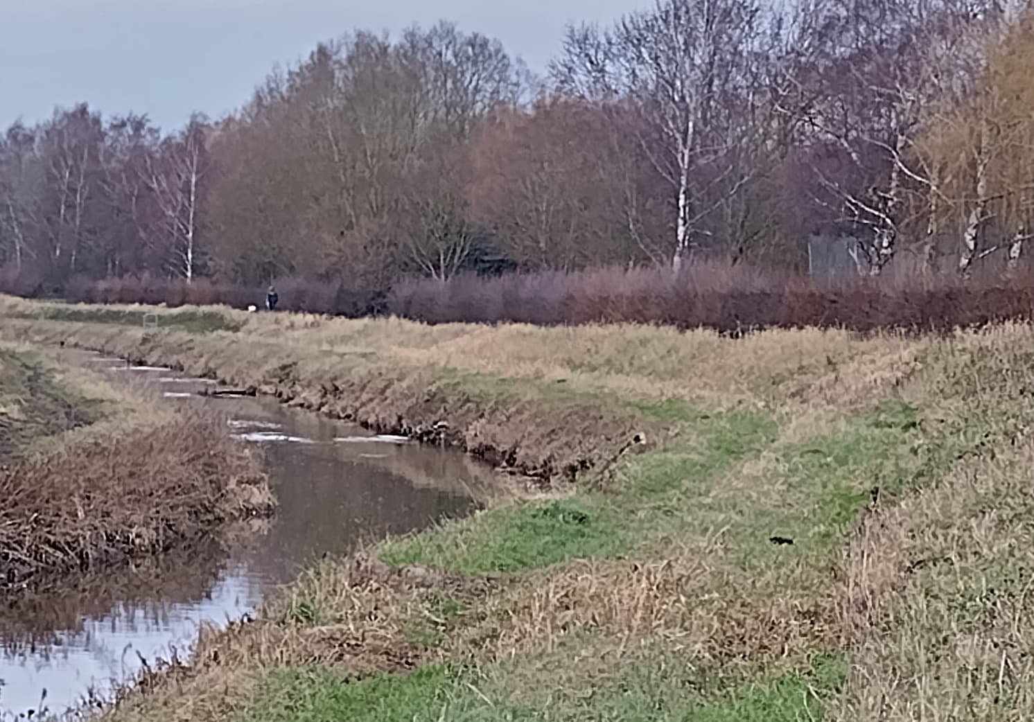
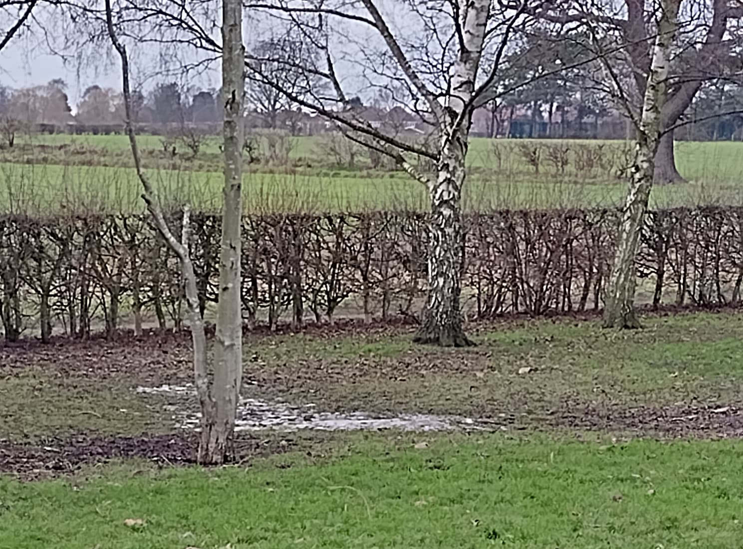
As a bit of an explanation, the river (which is quite low at the moment) has its normal banks, then there’s a flat bit to accommodate much more water when there’s more water in it, then a levee which is designed to be non-permeable so that (a) it doesn’t disintegrate and (b) water collecting on the land above is released only slowly back into the river. Surface water from houses and roads is often delayed by other collection areas but is then sent directly into the river, not to the area behind the hedge.
You can see quite clearly how water has collected on that bit of land and is being slowly released back.
This one doesn’t, but larger examples of this sort of thing like here might have water diverted into it by sluices (the “Flooded when upstream river monitoring station is 6m.03” note refers to the level at which these sluices are overtopped; less than that and you can’t predict whether it will be flooded or not)
It seems a kind of consensus is developing here!
One remark, I have the impression that the scale and complexity of dyke/embankment/levee works in Nederland is hard to imagine if you’re not Dutch! It’s a system of over 17000 Km of interconnected dykes reaching 2 or 3 stories high above ground level. To be practical, in this topic I am after mapping of dykes where you cannot see the other side if you are on ground level. And ground level in these parts of Nederland (the “polders”) is practically flat and well below see level. Rivers and bosom canals are also meters above ground level. We’re living on the bottom of gigantic bath tub, surrounded by water which keeps on coming in.
Dykes that high take a serious amount of land, and the slopes have lots of other uses. Dyke crests often widen and have roads, traffic junctions, bridge foundations, meadows, housing and even industry on them. The slopes also are used for a zillion other things.
That said, my question still is: if the slope is mapped as an area in addition to a crest line mapped as man_made=embankment, how does that enable useful rendering? And what rendering do we want?
My original idea was just a line at the toe, where the slope hits ground level. The rendering should show which side is the slope. In combination with the crest rendering this shows the extent of he slope.
I am not sure if a polygon can be rendered this way. I think you cannot render a part of the outline different from the rest, and at the top there already is a rendered crest line. The side lines preferably are not rendered.
To my knowledge, an area is always rendered in one colour and/or pattern. It’s probably in theory possible to e.g. render shading or fading pattterns, but I never see that on the maps I know. Which might be a lack in my knowledge… but If it is the case, what rendering of the area would give a good slope impression?
As I explore more threads in non-English languages while using Discourse newly-upgraded-to-version-3.0, I have noticed this “globe button” appearing more and more often. (It didn’t just days or weeks ago). I’m not sure how this works, how it knows that English is my first language or what makes it show up when it does, but it’s pretty neat! I’ve gotten used to using the translation built into my web browser (Safari), but that’s limited to very major languages (Spanish, French, Russian…). Google Translate is cumbersome (different web page, need to copy-paste…) and web-browser-buttons are good, but limited. DeepL is like Google Translate (but a different app), so having something “built in” to Discourse is great!
As a computer scientist and linguist, I’m impressed with the development of many such things, especially in the last five to ten years (and I’ve been watching this tech for at least 40 years). Everybody, begin to bow down to our new AI overlords!
Sorry to get off-topic from dykes and embankments, but this is a pretty impressive new feature, and I’m still discovering its potential and power. Thank you for calling it to my attention!
I agree that the question is less about “embankments” and more about “slopes”. I would think you need 2 lines to represent a slope, a bottom line and a top line, and some way to tell which bottom belongs to which top.
There is the relation type=area which suggests to define polygons through 2 non-intersecting ways, e.g with the roles “upper” and “lower” these could define a slope. If we can find a way to define slopes with polygons or another representation but without the use of a relation, it might be benificial but I cannot imagine how it would work.
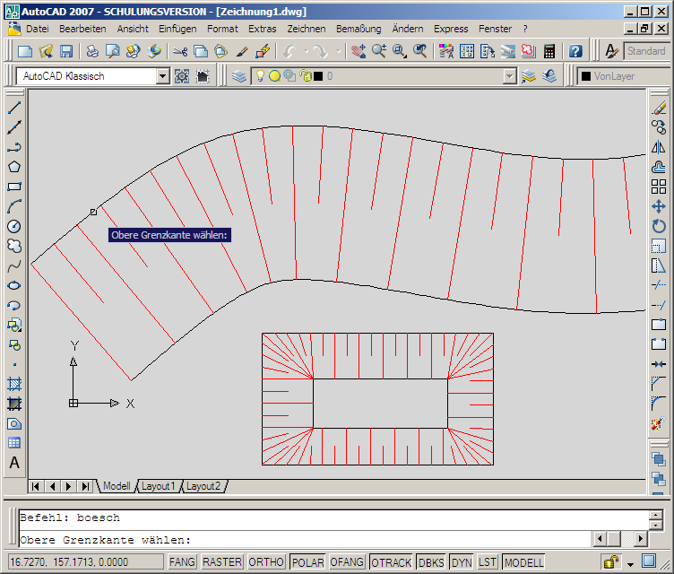
Regarding rendering, I do not think this belongs into the tagging discussion, but a typical way is with orthogonal lines, which alternate lenght or thickness (to express direction), like it can be seen here: https://etc.usf.edu/clipart/76800/76894/76894_topogrphsym_lg.gif
(in the upper right corner, “cut” and “embankment”)
I love examples…
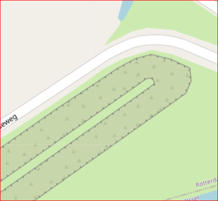
Here’s a picture of the origin of the river Rotte. The Rotte is 1m below sealevel and about 5m higher than the surrounding land! So the “river” is fed by the pumps moving the water out of the polders, and at the other end the water is pumped up again to get rid of excess water. In dry summers, the water can stream the other way, to keep ground water levels as planned (within 1 cm, with a temporary tolerance ca 10 cm).
You can see that the stump of the old mill is slightly below the crest, but the house behind the mill is level with the crest. Large portions of the land-side slopes both left and right of the river are meadow. Further on, there is no river any more, but the bank continues, it widens and a complete horse farm is on it, occupying crest and slopes. I am told by a more knowledgeable person that actually there are two dykes, one left and one right of the river, and beyond the origin the dykes join into one flatter dyke. Flatter, but not lower. Fo me all the more reason to map slopes instead of complete dykes. Then I can decide to map only the land-side slopes of each dyke, because I think the water-side slope is not that interesting for the map.
I think that mapping areas - whether the whole dike or just the slope - is not a good solution. At least with regard to a possible rendering.
In our data model we only have closed polygons for areas.
such areas then compete in the rendering with other areas, e.g. landuse=*
skillion roofs are not huge areas, clearly delineated and in most cases they have a clear direction. Dykes and embankments are often not straight but have frequent changes of direction. Either the direction of such an area cannot be specified exactly or a dike has to be divided into many shorter sections. This is not KISS
if you only want to render the edge again, you have this effect again:
With surfaces it is also difficult when a dike or dam merges into a natural elevation (e.g. dune).
Also other tagging aids like giving dike height and slope becomes difficult to determine on the ground. What is the basis for determining elevation? The sea level? The natural ground - to the right or left of the dike? The water surface? This is all nice to have, but not KISS.
I would prefer to leave the man_made=embankment for the embankment edge at the level of the top of the dike as it is.
I welcome a proposal to find a tagging for the toe line ( I think in Germany we say “dyke foot” for it) - e.g. man_made=toe_line. The toe of the dyke is, as @Peter_Elderson describes, usually easily recognisable, at least on land. If the toe line of the dyke is under water, then visually the riverbank is the relevant line (and toe line does not need to be mapped additionally).
The toe_line is easy to map and, depending on the quality, even recognisable on aerial photographs.
The only thing left to consider would be which rendering to propose for it.
The consideration of @SK53 goes in the right direction. It should just be a bit finer. I would just not render these differently sized depending on the slope.
For the toe_line, I can imagine small short fine strokes in the upward direction of the slope as a rendering.
If it should be technically possible - I have no idea, but I can imagine it - one can combine the (opposite) embankment and toe_line into a relation and a renderer can perhaps generate a hatching from it, as it is usually known from other map and CAD representations.
This is wrong in my eyes, it should always be the edge at the top.
Nederland has the term dyke foot, which includes part of the slope ending with the toe. I think the image is that the outer slope (water side) is steep like a heel, and the inner slope is like the front of the foot, ending with a slight elevation: the toe. Most of the time you will not see the toe elevation, because it is covered with soil, sand or grass. I am told that the expert eye can spot the toe easily on aerial photos and in the field. Since it is part of the construction that needs insoecting and maintaining, it cannot be fully covered without special constructions (concrete and steel, probably).
Btw, on our high dykes, the slope always has a flat section, often with a track on it, for dyke inspection and maintenance. Or not a track but a cycleway or minor (service or unclassified or even residential) road.
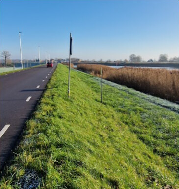
Example (my own photo, surveying a hiking route)
To the right of the track, the dyke has a reinforced_slope of about three meters, then a reed field sloping another 3 m down into the river water. The river level is tidal and also varies with rainfall upstream. The land-side of this dyke is much larger, because the land is yet several meters below the river level. This is one of the main dykes protecting my house, which is near the lowest point in Nederland, nearly 7 m below sea level. If this dyke breaks, only my solar panels and the chimney wil be visible above the water, and I’ll be sitting there with my wife and children!
The idea of representing the extent of an embankment (of a dyke or any other type) by two lines instead of an area would surely also be an acceptable solution but nevertheless the embankment IS an area and that’s why I believe it’s worth to think about tagging it as such. I am quite sure there will be ways to render the slope area, starting from the top line indicating the direction of the slope.
Anyhow I am aware that those extended dyke embankments being covered in parts with housing or commercial/industrial objects, roads, tracks etc. will not be easy to handle. From that point of view a solution ignoring the area and just indicating the toe line by an additional way with an appropriate tag has some charme for sure.
Maybe some misunderstanding? Peter wrote:
When looking at the embankment on each side of the dyke separately one can surely estimate the height of that very side from toeline to crestline. The same is done for other man_made objects which are difficult to measure as well and it is a valuable information imho.
I think this problem arises always when different landcovers merge. When the embankment of a dike is subject to a certain landuse like meadow no surface tag is needed. If it may be reinforced by rock for instance an additional tag surface=rock would not do any harm
Sure but even the wiki is not clear about this issue and the 200K embankment ways already mapped could well represent the toe line or even lie in the center of the slope. If a new tag for the toeline would be introduced now the documentation in the wiki should get some update with clear definitions where to place the ways.
I don’t think limitations of how we currently do things should affect what & how we map.
The precedent of mapping cliffs as areas is at least 12 years old, and I think things like defensive-work=glacis also come into this “mapping of slopes” issue, although most of the ones I could find a are also tagged man_made=embankment and are lines. Another example is a very wide set of steps (where area:highway=steps) can be used.
I think we DO miss the possibility of adding something like a width tag to a line (not width, because the convention is to map the top a sloped element) which denotes the distance from the top of the slope to the toe line. (Obviously this would work better with regular artificial constructions than cliffs).
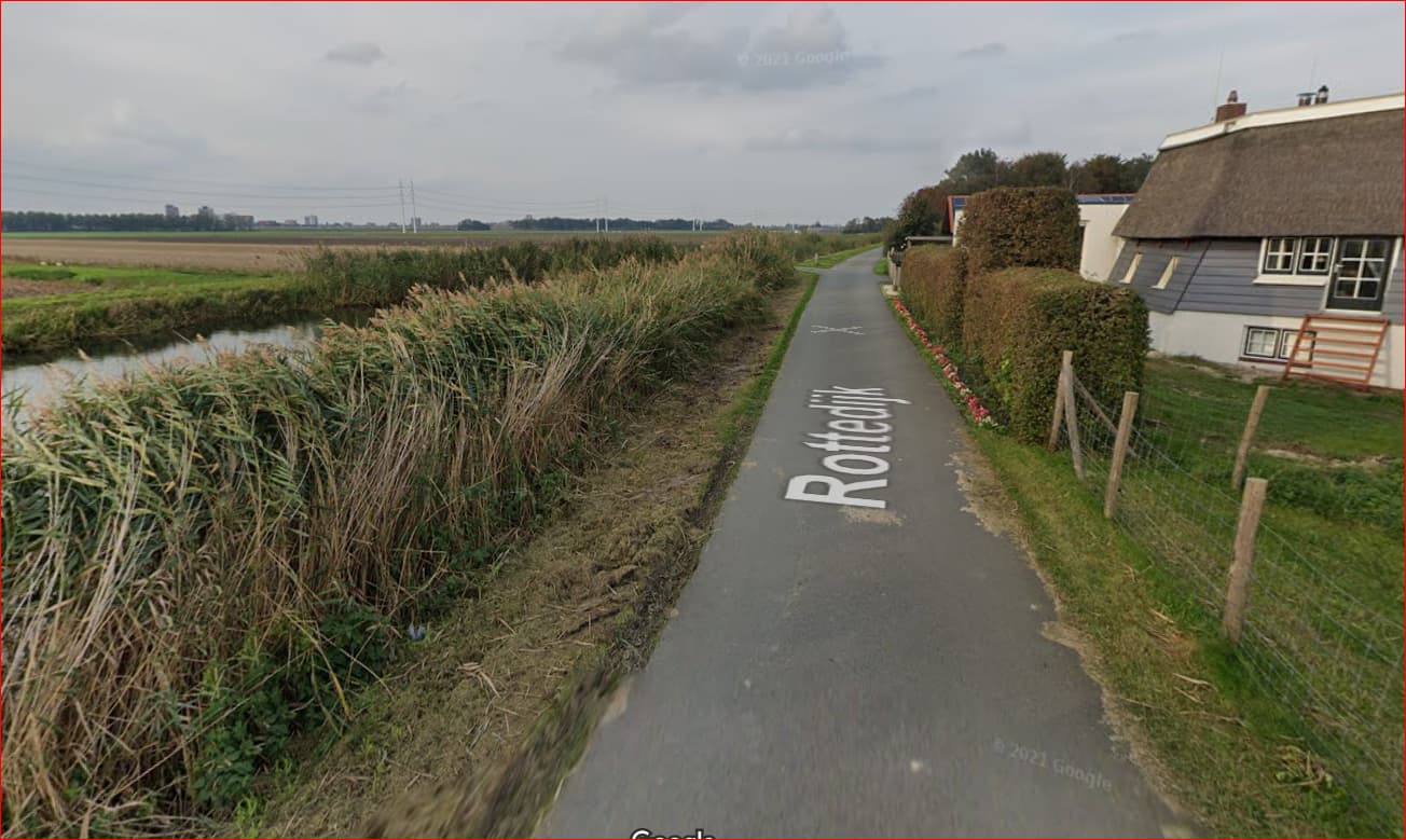
For those interested this picture might be an illustration for what Peter accurately describes as the Dutch living on the bottom of a bath tub: here is the best example photo I could find from my surveys that might convey this (Mapillary):
Please keep in mind that the canal is not like an aqueduct that is constructed above normal ground level: the canal is below sea level and we dug out the bordering land even lower (fossil fuels were popular in previous centuries as well…)
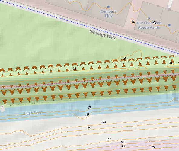
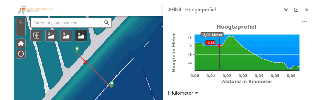
Cross section
Here you can see a lidar-cross section of such an embankment nearby (not this exact location since the buildings mess up the cross-section)
Source: AHN-viewer
On the left side:
Map with:
-grey: water
-blue: low-lying land
-green: high-lying land
-red line: the cross section (that you see in the image at the right)
-red cross: the border between the canal and the outside slope
On the right side:
Cross section:
-The flat section left of the red cross is the water level of the canal ( 2 meters below sea-level, the slope under water level and the bottom of the canal is not depicted)
-Directly at the right of the red cross is the outside slope of the embankment
-The crest is 1 meter below sea level and less then 5 meters wide
-The inside slope is about 25 meters wide (well defined and visible in the landscape) and goes down 3 meter
-Then there is a ditch and beyond that the flat inside the polder
This embankment is a circular feature with a circumference of some 30km
(and 25 m wide, so approximately an area of some 750 000 m2)
You need no knowledge to spot a crest; some awareness to spot a toe especially where it’s a bit hidden, and real expertise to see the complete dyke structure. I want to accommodate that in levels of mapping: all mappers can map the crest; more experienced mappers can map the dyke toe if they want; if the slope has special characteristics which we think should be mapped as a polygon, that’s an option; and it is also possible to combine an existing crest line and toe line to form an area.
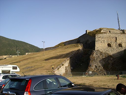
About other uses e.g. the glacis, if a sloping feature can be called an embankment with a crest and a toe, you can apply the embankment mapping. The glacis, possibly, though I can’t be sure that experts in that field would be satisfied with that teminology. But they could use the same mapping model, with more appropriate terms.
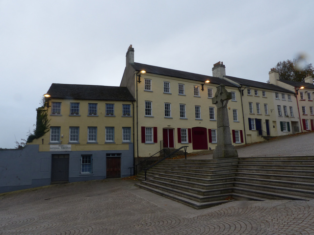
Step areas, same thing: I see a toe, a crest and a slope. The slope has a step part, which is probably mapped as one or more ways. Combine that with a crest line and a toe line, and I think it can be rendered reasonably fine, showing on the map what is there. Other attributes of the step area would probably warrant mapping it as an area. Such as, surface, name of the complete area, exotic form of the sides of the area, separate steps combining into one, that sort of thing.
One thing: the glacis and the oversized steps have well defined sides, and occupy a limited area. The side lines probably have their own attributes, e.g. retaining wall, fence, kerb, hedge. So the last option I gave above will probably apply sooner than with dykes: “It is also possible to combine an existing crest line and toe line to form an area.”. This then evolves into: “It is also possible to combine an existing crest line, toe line and side lines to form an area.”.

