Mapping embankments

How many toe-lines mapped as man_made=embankment do you think there are? So far, only your one example came up, mapped by you. IIRC you mapped one slope, the crest kink line and the toe line, bith as man_made=embankment.
I think this is an exception, and almost all mappers use man_made=embankment to geotag the upper line of the slope.

I have not yet seen any case of a full two-sided embankment mapped only as an outline along the toes.

The consequence of changing the definition on rendering in those cases are none. The rendering remains exactly the same. The impression that it is a pit instead of a slope, also remains the same.

I don’t know, but far more such examples have come up in just our discussion than the one example you mention now:

  • The discussion you linked here in the Dutch forum started with an example in Germany by a another mapper with both toe-lines mapped (which the OP called a nice way to depict the embankments)

  • as I wrote here I first followed the narrow-interpretation for tagging man_made=embankment, until I saw work from yet another mapper who tagged the toe-line as such, read the wiki again and realised that it does not exclude using it for the line around the actual embankment (the toe-line). I think it was the work of another mapper here

  • and I am in good company realizing that the wiki is not clear cut on excluding usage on the toe-line, for example this mapper wrote

Which translates to (Deepl ; [my addition about tense in Dutch original text] ) :

I read [past tense] the wiki for embankment as tagging the stitch line/crown edge of the embankment. But he does not, on re-reading, rule out that you could use the tag for a footline;

  • And others in this English thread have concluded as well that you could read the wiki in the broader way as well. Especially since the narrow interpretation can in some cases be very counter-intuitive as described here.

  • And more mappers will held this opinion on one time or another and have mapped accordingly, as you can see for example here: without much effort I stumbled upon a site with some 50 embankments where the toe lines are tagged by yet at least two different other mappers.

I am not saying this is ideal ( for instance I wonder if the toe lines are drawn in the correct direction), but the suggestion that usage for the toe-line would be extremely rare is simply not supported by the examples of mapping and opinions that have been presented.

And I would still very much would appreciate your reply (or better proposal) on the question of definitions for scope in this discussion

True, there are more examples. Still I think the regular use of man_made=embankment is just the crest side line. “Nice way to depict embankments”, I disagree.
The example of the military base in Den Helder shows why it’s not a good idea to map the toe lines as man_made=embankment. The mapper probably thinks it shows embankments, because (s)he knows what is there, but if you don’t, it shows a collection of curiously formed (snake?) pits. I’ll zoom in a little…

To the left, a sea dyke has its crest mapped. Outside the embankment is another embankment line, where another section of the slope starts, there is a banquet (berm) there. There is no toe line, but there is a fence which gives an impression of the ende of the slope, just above the outer embankment line. And the water edge marks the end of the lower slope. This looks OK.
A toe line could improve the rendering by showing the berm with the fence better.

The military embankments would certainly profit from a differently rendered toe line.
The outer lines are drawn with the high side to the right, not the low side. You could draw them in the other direction, but then they would look like another slope section, just like the reinforced slope of the sea dyke.

I said in the beginning of this discussion that I thought the wiki did not rule out using man_made=embankment for the toe line, which was my first impression. I was wrong; the wiki doesn’t explicitly say the tag is just for the upper line where the slope begins, but taken as a whole, you can’t fit a toe line in the description and the examples, and it is clear that it only applies to the upper line of one embankment slope. Anyone who wants to quote me on this, please do not quote my older impression!
I do think it would be wise to state this explicitly in the wiki, and you can quote me on that.

Addition to the navy base mapping:


These are not embankments, but fuel storage tanks. I think we have a serious case of mapping for the renderer!

I try to avoid the discussions about the terms, and concentrate on the information needed (mainly) for renderability. (Is that even a word?). I think the initial confusion is much less now. Yes, embankment is the whole thing, but also often used for just one side, and there are one-sided embankments.

All the technical parts, categories and variations and the terms for those things, it’s nice to have a model and terminology for describing things, but we shouldn’t let progress depend on that. I think whatever models and terms come up, the basic information where the embankment slope stops is always needed.
I do not want to impact the installed base for man_made=embankment as the upper border of the slope. Which leaves deciding on how to map/tag a lower border of an embankment slope as the singlemost piece of information needed, to get any further. No matter what the exact definitions are.

1 Like

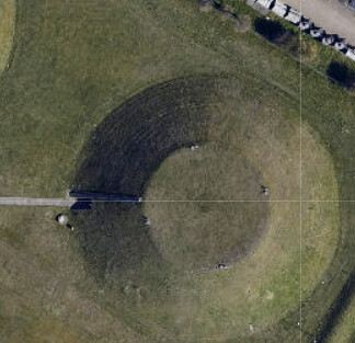
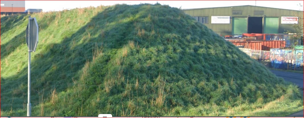
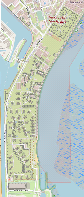
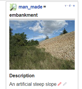
I think this example is off-topic. And that kind of judgement seems a bit excessive in this case whether or not there is a fuel storage in the core of the embankment, observers still see an artificial slope covered with grass. And the feature is also tagged as storage tank in OSM.
image

But more on-topic I think it is good that you mention the principle of tagging for the renderer. I find the constant focus on how nice or not nice examples render in current Carto instead of how structure of the data we enter in OSM relates to the real world features we aim to describe worrying.

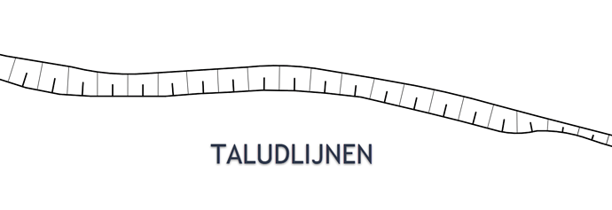
I think everybody agrees that the current mapping scheme for embankments is not sufficient and that mapping toe lines -and being able to distinguish them from crest lines is a valuable addition.

But if we rush to just ivententing another line and focus on fun things like tagging, the end result might not be an improvement but make a bad tagging scheme even worse (see some of the considerations mentioned earlier)con.

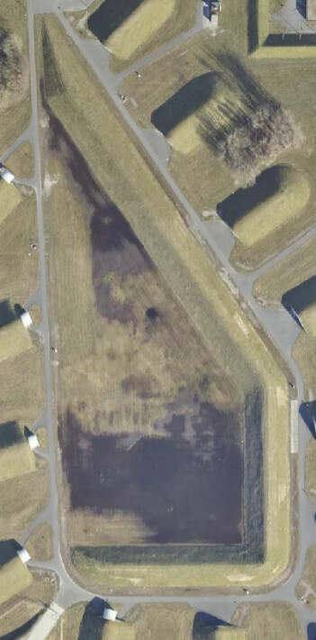
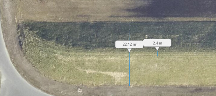
I found this to be the most worryin example of (incorrect) tagging for the renderer at the cost of a geometry that is representative for the feature we aim to describe:

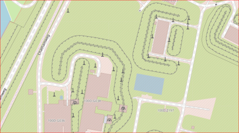
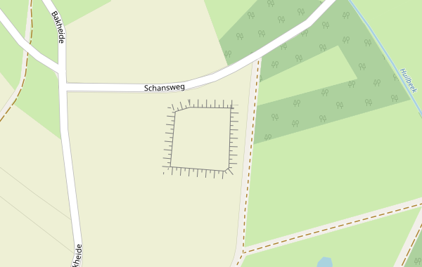
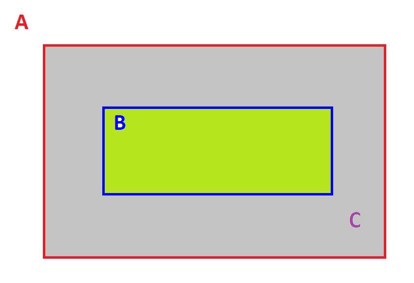
In the Dutch thread you defended mapping this embankment:

like this:
image

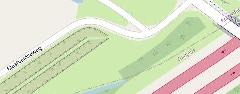
with a break in both the toe-line and the crest line -where in reality they continue. Stating:

and just as with a track on landuse, you can then craftily map the landuse on either side separately

That might look nice in Carto with a 3d like effect at the break, but that resembles the canonical example of what NOT to do when it comes to incorrect tagging for the renderer.

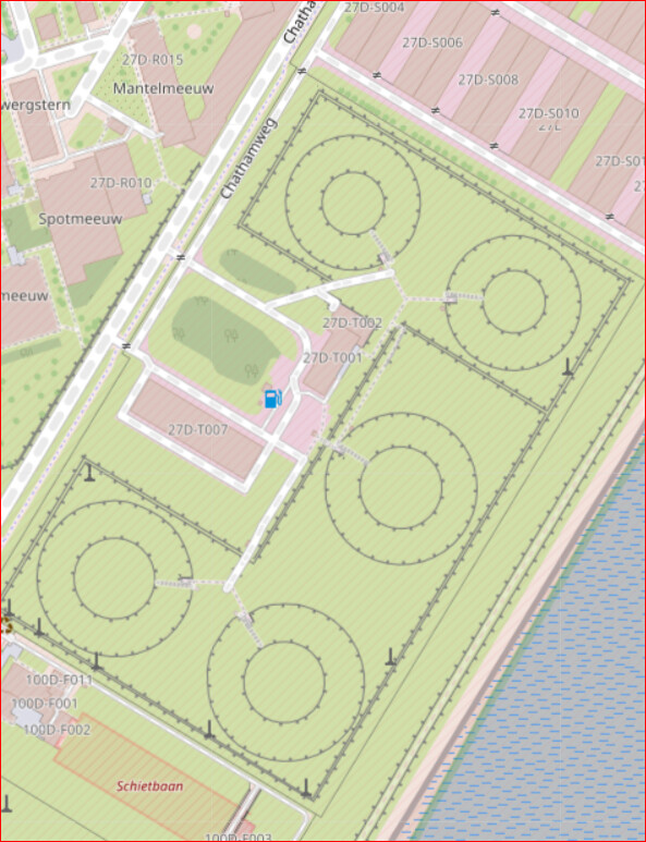
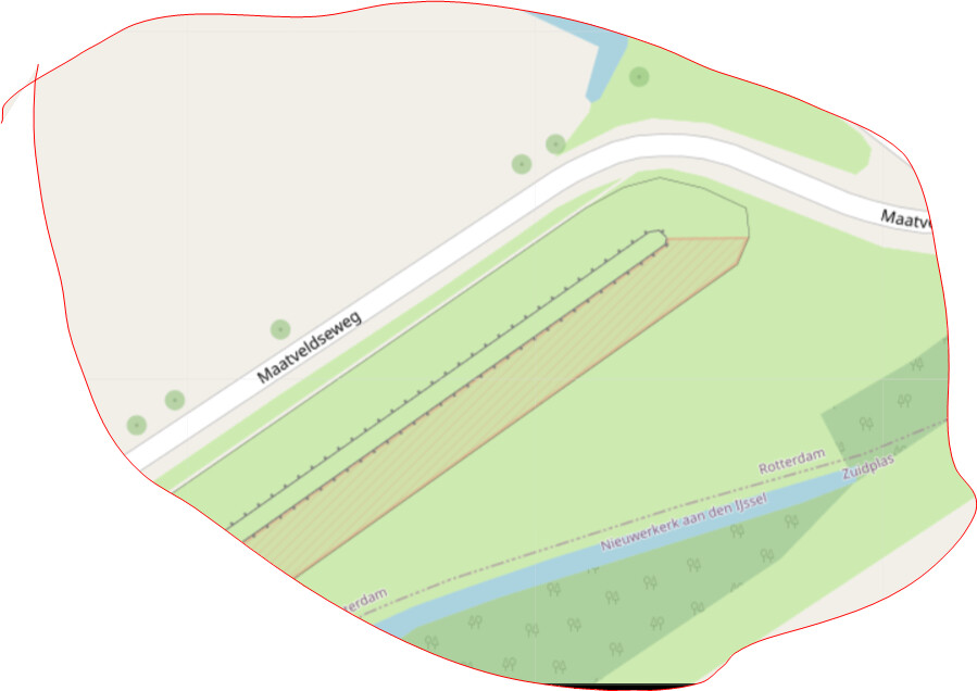
And after removing the optical break the alternative which is geometrically much more correct was discarded -like the examples in the post above, looking at current Carto images, stating:

You want a solution that also looks like a dyke to others.

While as a geometry the second variant is much more correct, and has the potential for both renderers and other data users to give usable results.

But to do so we must first improve the tagging scheme so that we have a scheme with meaningful terms in relation to each other and in relation to the features we aim to describe, so we can distinguish both the circumference of the different parts and their relations.

Rendering is at the end of the line, our job with tagging is just to hand the renderers the information they need and not cut corners to get nice looking results quick.

No I did not defend that, I rejected that. it was an example of what could currently be done in mapping but with a wrong result, showing that there is a lack of information for a renderer to do this better. Hence the need to add at least a toe line which can be rendered differently. The break represented a path. It does not help to keep quoting me out of context!

As I said before, I focus not on the actual rendering, but on the information needed to render embankments better. At the same time, better rendering is the main goal here, and that requires mapping. When thinking about this, how it could be done and how that would work out, examples wil show a rendering.

Mapping the toe line as man_made=embankment because then you see the line, even though it does not fit the wiki, that is classical mapping for the renderer. I would like to see that change into mapping the toe line with its own tag(s), and I expect rendering to follow later as the information to make it look better becomes available.

Do you think mapping a toe line does not correspond to the real world?
Can you think of a workable data structure for richer mapping of embankments that would not include the toe line, be it as a separate line or as part of a polygon or area outline?

I think the bottom line is that we all want the same thing: a better representation of the extent of a slope in the database and on a map. For you Dutch, the dikes are the most important, that’s understandable. But it should also work for other very similar things, whether it’s a dyke, a railway embankment, in road construction, noise barriers or construction pits and fortifications. The basic principle of an embankment is always the same: there is a top edge, a sloping surface and a bottom edge. Mappers can recognise and map these three features even without specialist knowledge.

Keep it simple …

There are several ways that can lead to this goal:
First, we accept that embankment=yes is just an additional information at another way, that it runs on an embankment, but has no information about the width of the embankment. I think this is indisputable and needs no change.

  1. man_made=embankment is in use, far predominantly representing the crest_line between crown and slope. Other uses in the middle of the slope or at the toe_line are considered incorrect because either the wiki was misleading (not in my eyes), the mapper misinterpreted the wiki or deliberately used for the toe_line to force a render (mapping for the renderer).
    The wiki needs to be clarified: man_made=embankment exclusively only for the respective top edge of a slope.
    The wiki is to be supplemented: a new tag for the toe_line, e.g. man_made=toe_line or man_made=embankment_toe or …
    This toe_line will also be visualised by the renderers in the future. This problem should be solvable.
    advantage: very simple!
    man_made=embankment remains untouched, most mapped slopes can remain unchanged, only some wrong ones have to be corrected.
    Desirable would be a modified rendering with the fine strokes (as I know it from most maps and from plan drawings). This makes the mostly even slope better distinguishable from rather steeper or vertical and irregularly shaped natural=cliff.
    Disadvantage: it is not a tagging scheme, it is in man_made=* with much else.

  2. we use man_made=embankment as the main tag in future and extend it as a tagging scheme, e.g.
    embankment=crest_line for the top of the slope surface and
    embankment=toe_line for the lower edge where the slope meets the ground
    Advantages: clear tagging scheme, expandable. Existing man_made=embankment could be searched for specifically and extended by embankment=crest_line after visual inspection (while adhering to the rules for mass edits) - in doing so, visual individual inspection also finds the cases where it has been mapped in the middle or at the toe so far and can correct it immediately.
    Disadvantages (that I see): possible conflicts with existing embankment=*.
    The combination of man_made=embankment and embankment=toe_line is factually rendered wrong (like the crest_line) by renderers that only evaluate the first one. This can lead to more confusion overall at first.

  3. We invent a completely new tagging scheme with a new main tag. The big disadvantage is that this is not rendered at all at first. However, such a completely new scheme could be run in parallel for a while until the renderers also display it.

Personally, I would prefer the first option.

1 Like

Been following with interest, so a couple of questions re possibly connected options.

How about cliffs? We currently only map the top edge of a cliff - should we also map the bottom?

& do we then turn any new embankment idea around, & also us it for the top edge of cuttings?

I wouldn’t use man_made for cliffs. You could copy the idea, though.

Cutting can take the form of a retaining wall, thus that would not be an embankment, I think.
If the cutting on one side of the road is in fact a one-sided embankment, I would not hesitate to map it as an embankment.
So two OSM-embankments, back to back, form a dyke/levee/railway embankment/road embankment; two OSM-embankments, toe-space-toe can form a cutting. When there is a road or railway in between, I don’t think I would map a toe line, though. Unless… well, the cutting could widen , maybe for a gas station or rest area… then maybe a toe line would be nice on that section.

(Disclaimer: I’m thinking out loud. If valid counterarguments emerge, I might change my mind, in that case please don’t hold this against me!)

I (for one) would like to heartily encourage “thinking out loud” in OSM’s Discourse forum (here).

This is, and should remain, a friendly, productive, collaborative space to do exactly that, this thread is a good example of it. There’s some fascinating stuff being said here and the fact that the discussion is so lively and diverse I find wonderful. There are ideas that cross over between railway mapping, natural mapping (like cliffs from @Fizzie41), stern and necessary reminders that OSM is a database (with renderers and use cases properly stated as “at the end of the line” and “only need the data that they need”) and some great rhetorical devices like “Advantages and Disadvantages.”

Keep up the good discussion, everybody. This is a bright, vibrant topic, with awesome pictures and thoughtful posts.

BTW, as a native English speaker, I would say “renderability” is a word, though purists or dictionary publishers might disagree. (My excellent dictionary shows “-ability” as a listed suffix).

1 Like

How could a toe line look on the map? Of course, it’s up to the renderer, but the renderer shoud get some idea of what is requested. I have heard mentioned a rendereing as a line with short side lines at the slope side. When the top and bottom edges are close, this would mean overlap. It also is quite similar to some renderings of the top edge I have seen.

I was thinking of a light gray/dark gray double-line, giving an impression of a kink line. Dark side would be the slope side. This would work on any background, I think. It’s the same trick used for undertitles, to ensure the letters are visible on light and on dark backgrounds in any colour.

Impression (making very clear that I’m a disaster when it comes to images…)
I hope this conveys the idea.

This is a piece of an actual embankment toe line. And a very crude double-line mimicking it. I think something like this, made into a line by someone who actually knows what (s)he is doing, would do the trick. It’s direction dependent, just like the top edge.
If the mapping aims to draw the toe line in the same direction as the top line of the slope, the instruction would be that the slope side is to the left of the way (dark), the flat side is to the right of the way (light).
The light side is the right side.

Mapping the upper and lower slope edges can’t be that difficult, various CAD software can do that too.

Examples

@Kogacarlo have already shown it here

Connecting the upper and lower line with fine strokes may not be trivial for renderers with the possibilities of OSM.

That is why I am thinking of rendering the two lines separately as a first step:
The upper edge (crest_line) of the slope (in the image this is the lower line!) has alternating shorter, thicker strokes and longer thinner strokes at somewhat closer intervals. This is - at least as far as I know - a widespread form of representation of the upper edge of a slope.
That this can be done easily has @Kogacarlo already been shown:

The lower edge (toe_line) of the slope (in the first image this is the upper line!) is to be mapped and rendered separately. This way has only thinner strokes at somewhat larger distances.

The length of these small strokes is to be chosen in such a way that in most cases they are opposite each other in the different zoom levels and at most touch each other. If they form a gap at larger distances, this is probably not a problem; a sighted person then unconsciously completes this in his or her brain when looking at a map.

In a second step, we can consider whether we can connect crest_line and toe_line with a relation and this enables a renderer to connect both ways with fine lines.

OSM Carto has a different rendering of man_made=embankment, just a line with some dots (giving the impression of shark’s teeth) at the lower side. Very suitable for a general purpose map. I see no reason to ask for a change there. I think the lower edge could be rendered even more subtle, to prevent railway-like appearance when top edge and bottom edge are very close (steep slope). A simple line (lighter than the top edge line, maybe a bit less sharp) would already show the extent and shape of the slope, and if there is a way to hint at the slope side very subtly, that would be a bonus. Actual non-scaling side lines - I think it’s too much.

I think connecting/separating side lines of lower and upper edge is not an issue.

To (maybe later) show the entirel slope as shaded or line shaded (Dutch: gearceerd, from the verb arceren) a relation with the top edge line and the bottom edge line woud be needed. Side lines can vary too, in complicated cases like the railway-crossing-canal example I gave. So we are talking about shading an area. As it happens, OSM already supports relations representing an area, and rendering such areas is pretty much standard.

Of course, I know.

My idea was to create a visual relationship between the two lines at the same time. That’s why I think the bottom line can look similar but still distinguishable and should have an additional mark that points upwards (like the teeth of man_made=embankment point downwards).

Further suggestions are welcome

I cannot render, but I can cheat to make it look like what I want to see! (aka mapping for the renderer.) Here I have an impression of an embankment with two different renderings.
The crest is delimited by the two crest lines, with just landcover between them. The north slope, I mimicked a double-line (white-gray) using a break in the grass cover and a feature that produces a gray line. (Note: because the white break scales when zooming, and the line does not, I had to choose one zoom level for the picture.)

The south slope, I used the line feature again, and this time I combined them in an area that has a rendering over the existing landcover.

I think the north slope subtly produces the right effect by just indicating where the slope stops. The south slope is not bad either if you ignore the colour, and it emphasizes the slope itself. It is a little too emphasized for my taste, on a general purpose map. I am mainly interested in the edges; the slopes themselves are just landcover.

Thanks for suggesting a couple of routes.
My preference would be a variant of option 2:

To take the simple example of a “free standing” embankment as a starting point:

In a schematic form this can be described as:

With the following features in the real world:
A : the embankment (the total of slopes + crest)
which consists of the following parts:
-B : the crown
-C : the slope(s)

To have a geospatial representation with the level of detail we all seem to aspire need two geometries:

  • the blue line (that traces the crown-line)
  • the red line (that traces the outside of the embankment ; in this case: the toe-line)

My preference would be to tag it something like

  • blue line (crown) : man_made=embankment ; embankment:part=crown_line
  • red line (outside of embankment) : man_made=embankment ; embankment:part=toe_line

Accompanied with an advice to renderers:

"most man_made=embankment without embankment:part=* are assumed to follow crown_lines; therefore it is suggested to render those as you do with crown lines

And in addition - to make the relations between the tagged lines explicit and allow for both better rendering and data-analysis (what is the area of slopes / crowns etc.) as an option :

- A multipolygon relation
with a new tag like area:embankment ?? (like area:highway)
Red line: role =slope
Blue line: role=crest

If it is already obvious enough from the main tag that the slope rises from from the outside to the inside, then these roles will suffice. If not the role for the red line could be slope:up or slope:down (seen from outside to inside) and for the blue line: crest or bottom
That depends on whether the main tag would include sloping pits (as opposed to elevations) as well, such as this example mentioned in wiki-Talk :

Disadvantages:

  • Not all mappers like to use man_made=embankment for the outline of the embankment

  • The optional multipolygon relations can be seen as complex by some

  • We have to figure out how well this model works for other cases (such as berms) and one-sided slopes (yet I think it is good to first find common ground for handling a simple case and after that take on more complex cases)

Advantages:

  • Avoids awkward tagging scheme / instruction in which the general term man_made=embankment is only used to trace the outline of the crown and not for the embankment as a whole (“trace the outside of the embankment and tag it with man_made=toe line; trace the none-sloping crown in the middle of the embankment and tag it with man_made=embankment”)

  • Leaves both current usage of man_made=embankment for crown (probably most common) and toe-line (less common, but no so marginal that it can be ignored) untouched

  • No conflicts with existing embankment=* ( which is already in use as a property-key
    on elements that themselves are not embankments, such as highway=* )

  • Multipolygon relation gives potential for both better rendering and data analysis

I think it is much simpler to just tag man_made=embankment_toe (or another key/value) to a way at the toe line.It contains al the information needed to tag any embankment, even a freestanding embankment.
I think it strange to first throw the two lines together with one main tag, then separate them with a secondary tag, That is asking for trouble, I think.

The instruction:

  1. draw a way on the upper edge of an embankment slope and tag it as man_made=embankment;

  2. (optional) to tag the lower edge, draw a way on the lower edge of the embankment slope, and tag it as man_made=embankment_toe

  3. (optional) to add area information for the embankment_slope, a multipolygon can be used having the upper and lower edges as outers, and two untagged ways to close the outline.

This multipolygon area stuff could be used even now, you don’t need a toe line for that. Just the upper edge line and a non-tagged way around the sides and the lower edge of the area. It can contain any tags you like, if there are use cases for such data. If you give it a landuse or natural, it will show up on OSM-maps as such.

The lower edge line can go all the way around a free standing embankment, no problem. Just as the crest of a free standing embankment can be tagged with a closed way all around. The combination of the two closed ways Is the embankment. A berm (banquet) simply cuts the slope in an upper slope and a lower slope, if it is important to the mapper that can also be tagged very easily: just map the upper slope and the lower slope as separate slopes.

It’s also no problem to tag a freestanding embankment as two slopes with touching ends. Or, if there is just a sloping start but never a sloping end, the mapper can also choose to us one upper edge line and one lower edge line, or map both sides as separate slopes meeting around one end.

Many embankments will not be so simple. But they all can be viewed as a combination of embankment slopes. Such as in the example of the railway embankment crossing over the canal embankment. Separately tag the lower embankment slope and the higher embankment slope separately, each with it’s own upper and lower edges.

If there are other features on the slope, crest or toe, the ways can just go around, or stop if there is no toe or crest.

I really don’t see the value in sort of encompassing logical approach. Embankments may be complicated on the inside, but on the outside they are relatively simple structures which can be described with (combinations of) a few simple elements.

2 Likes

I don’t see how that would be more trouble than using the general term man_made=embankment only for a portion of the actual embankment en tracing the whole of the embankment with a tag that indicates only a portion of the embankment.

That would be so illogical and counter-intuïtive that it different mappers will do different things (and will do different things at different times, just like you changed your view on how to interpret the wiki twice).

See the current definition and image for man_made=embankment
image

And consider an actual embankment:

If man_made=embankment in general terms means the whole of slopes and crest and is defined as a slope in the wiki, it makes no sense to only use the key man_made=embankment to trace the outline of the 2 meter wide crest in the middle and not for the 22 meter wide actual embankment.

If you would ask people to point to the location where the embankment starts, most will point to the toe, not to the crown.

And the reasons to create a wiki definition of embankment that is contrary to the regular definition of this term are, in my opinion, by no means strong enough: the principle of using a main tag and specifying it with a second tag is not strange or uncommon, it makes it clear that the two tags and/or elements are related in some way and it is done in different forms, for instance building:part or natural=water combined with water=

I do not share this view. Or have you done an empirical survey?

The difficulty begins with the fact that embankment is a word that can have different meanings.
embankment in the sense of fill, elevation, dam or earth wall)

or embankment in the sense of a slope or incline.

I share Peter’s view. man_made=embankment is an established tag that is predominantly used for the top of a slope. Making the distinction between crest and toe_line only with a subkey will initially result in a broken rendering for many map providers. This has the great risk of not catching on.
If tagging scheme, then a completely new main tag that can be used in parallel with the existing one until it catches on and completely replaces the old tagging. This is what happened with waterway=riverbank, which was replaced by natural=water + water=river. For a new main tag, however, another suitable and comprehensible term must first be found; embankment is already in use.
Apart from that, such a fundamental change needs a proposal.
An extension with man_made=embankment_toe or another good term will probably be easier.